You are using an out of date browser. It may not display this or other websites correctly.
You should upgrade or use an alternative browser.
You should upgrade or use an alternative browser.
Converting a hubmotor to a middrivemotor
- Thread starter crossbreak
- Start date
crossbreak
1 MW
The chain disconnects the mac from direct shocks from the wheel. The better than mounting it to a rim IMO
EDIT: Also, these hubmotors use plastic gears. The do a lot of damping. That's great plus compared to steel gears.
EDIT: Also, these hubmotors use plastic gears. The do a lot of damping. That's great plus compared to steel gears.
waynebergman
100 kW
On the subject of shock to the motor I am worried about the key pin shearing under stress as I have sheared a key pin in my mac before, set up as a stock wheel mount not as a mid drive however. Whiplash has replied to an earlier question I had regarding how this stress to the key pin is helped in a mid drive set up but I am still not sure if I really get it. Can someone try and explain again for me please how this load on the key pin is reduced when going with a mid drive? When bouncing up a hill under power and the rear wheel spins up under no load and then makes contact with the ground again is how I sheared my first key pin.
Thanks Wayne
Thanks Wayne
If your midddrive goes thru the bikes gears (or another multi-ratio transmission), then you can shift down to a lower ratio to ease stress on the motor itself--it's maximum speed is reduced, but it's torque is increased, via the gear ratio. Then as you reach a higher speed where load is reduced, shift up to a higher ratio to increase your top speed.
Similarly, if you were to use such a lower gear ratio in a single-ratio transmission, but raise the voltage limit (higher voltage battery) supplied to the motor at WOT, it'll do the same thing, but with the top speed raised (assuming the controller can handle the higher eRPM of the motor at that point).
Similarly, if you were to use such a lower gear ratio in a single-ratio transmission, but raise the voltage limit (higher voltage battery) supplied to the motor at WOT, it'll do the same thing, but with the top speed raised (assuming the controller can handle the higher eRPM of the motor at that point).
crossbreak
1 MW
great explanation, amberwolf, but that does not tell us why the key pin should see more stress. IMO the stress to the key pin is defined by max phase amps or torque of the motor. It should not change if the motor is converted, making the axle rotate.
It does change if one increases phase amps, since one thinks that it could stand this due the increased heat rejection and torque output of the planetary drive. But this is not the case. Torque output is increased, but the phase amps limits stays the same as for a hub mount config. Thing is, that the axle rotates slower than the hub would (more reduction and so more torque output from the planetary drive), as already discussed.
Why and how can we now have four times the continuous power output of a Hub mount config?
1st:
The normal max power output of a Hubmotor is not continuous, it will overheat at max power out. Max continuous power out is half of the max power out for most hubs. Due conversion we increased heat rejection a lot, so we can now push in max power forever, nothing will overheat.
2nd
We can double input voltage, since we can now use more reduction and derailleurs. So we wont spin the motor double as fast, we just dont have to leave the good power region. This is only the case if the whole Middrive is geared to or near to human speed and can make real use of the derailleurs. One has to half the battery amps now, so one that the phase amps stay the same. This is only 100% true, if the controller config for the Hub mounted drive was already perfect, which I have never seen in my life.
Which controller config should we use?
The controller has to be programmed, so that one has a flat torque curve. Almost 100% of all controllers I had hands on, have a horrible gear-killing config, which prevents the user of using even only half of what his motor could do. Most controllers come with gearless-direct-hubmotor "friendly" setup, pushing huge phase amps into the motor at start-up to conceal poor efficiency/torque output at low speeds/on hills. This then kills most geared hubmotor plastic gears, and people say that they are made of peanut butter, which is not the case. People who tell stuff like this mostly do not know what phase amps mean at all . This is why we have a wiki now, that tells everybody
  Still, there is some truth in these words, since if one overheats his hubmotor, the gears will melt - just like peanut butter.
It does change if one increases phase amps, since one thinks that it could stand this due the increased heat rejection and torque output of the planetary drive. But this is not the case. Torque output is increased, but the phase amps limits stays the same as for a hub mount config. Thing is, that the axle rotates slower than the hub would (more reduction and so more torque output from the planetary drive), as already discussed.
Why and how can we now have four times the continuous power output of a Hub mount config?
1st:
The normal max power output of a Hubmotor is not continuous, it will overheat at max power out. Max continuous power out is half of the max power out for most hubs. Due conversion we increased heat rejection a lot, so we can now push in max power forever, nothing will overheat.
2nd
We can double input voltage, since we can now use more reduction and derailleurs. So we wont spin the motor double as fast, we just dont have to leave the good power region. This is only the case if the whole Middrive is geared to or near to human speed and can make real use of the derailleurs. One has to half the battery amps now, so one that the phase amps stay the same. This is only 100% true, if the controller config for the Hub mounted drive was already perfect, which I have never seen in my life.
Which controller config should we use?
The controller has to be programmed, so that one has a flat torque curve. Almost 100% of all controllers I had hands on, have a horrible gear-killing config, which prevents the user of using even only half of what his motor could do. Most controllers come with gearless-direct-hubmotor "friendly" setup, pushing huge phase amps into the motor at start-up to conceal poor efficiency/torque output at low speeds/on hills. This then kills most geared hubmotor plastic gears, and people say that they are made of peanut butter, which is not the case. People who tell stuff like this mostly do not know what phase amps mean at all
crossbreak
1 MW
Which derailleur config should we use?
We need a config that makes us use the power of the motor most efficiently, without having to shift too often. If there are to many gears to shift, we will get lazy and wont do it properly anymore. Since we now have a strong motor, it seems like we dont need it. But this is not the case
Hubmotor configs are single speed. So if we add 260% gear range of a normal derailleur cassette, this is more than our motor would have ever dreamed of. Thing is, that it does not make much sense to have more, since it will be barely needed. No matter what we want: Max speed or max climb, it's within 260% gear range.
Example: 1500Watts output motor (2000W input)
Max speed that we can get is 35mph, since wind drag is so large at 35mph, that we need the full 1500W to face it. If we now want to climb a 30% hill, we also need the 1500W. We just have to decrease speed for 2.6times, going only 13mph. If the hill is steeper than 30%, then this will be the first time that we have to pedal
as already said, I can recommend the 7-speed HG-50 13-34T. It has good range (<260%), it's more durable than expensive 9/10/11-speed cassettes and it's even cheaper.
It has only 7 gears, so we will shift less often and more precise. IMO 5 or 6 gears would be perfect, but I have not found such a cassette.
Cost for cassette and chain is really important, since even this great cassette does not make it very long
One should NEVER use an alloy drive sprocket (like the cyclone freewheel crank), since then the chain and cassette has to be changed even more frequent.
Whiplash
1 MW
- Joined
- May 10, 2010
- Messages
- 2,906
Another trick I have used with good success is to apply some loctite "retaining compound" to the key, shaft and the clutch mounting ring after a thorough cleaning with acetone or the like. It is incredibly strong and likely the key will be fine. I would gamble you could delete the key completely and it would still be fine. Its that strong..
crossbreak
1 MW
great stuff whiplash! I will add this to the article/how to with pics/analysis aft 3000km of use, i'll write in spring 
crossbreak
1 MW
After i analysed my mount I must say that it starts to bent. Only 1-2degrees, but noticeable. Went out for some trial lessons and I do about phase 60amps max atm, wanna ride it to destruction... it's much harder than I thought 
I will upgrade for 3mm thick mounts ASAP. Now that I've got the hollowtech2 BB that shoul be no problem.
ALSO I will shorten the distance between BB and motor as much as possible with the new sheets. Now it's great the I use a small SWXB, with a MAC that would be impossible/look ugly
I will upgrade for 3mm thick mounts ASAP. Now that I've got the hollowtech2 BB that shoul be no problem.
ALSO I will shorten the distance between BB and motor as much as possible with the new sheets. Now it's great the I use a small SWXB, with a MAC that would be impossible/look ugly
full-throttle
1 MW
Is the efficiency data for BPM available? Let me know if you need measurements (lam thickness, coil AWG, phase inductance, etc..)crossbreak said:some bafang BPM winds..
hope there will be some one who converts one soon!!
full-throttle
1 MW
As requested:
BPM 500W Code-9
Phase impedance 70mOhm
Phase inductance 275uH
9 turns x 10 strands of d0.56mm (23AWG)
34 lams 0.5mm
18 teeth 17mm wide x 10mm deep x 14mm high
Stator dia 130mm
Air gap 0.5mm
Magnets 8 pairs 18mm wide x 2.5mm thick
Flux ring 6mm thick
BPM 500W Code-9
Phase impedance 70mOhm
Phase inductance 275uH
9 turns x 10 strands of d0.56mm (23AWG)
34 lams 0.5mm
18 teeth 17mm wide x 10mm deep x 14mm high
Stator dia 130mm
Air gap 0.5mm
Magnets 8 pairs 18mm wide x 2.5mm thick
Flux ring 6mm thick
crossbreak
1 MW
Thx a lot full throttle! Looks like this motor is much more efficient than the smaller SWXB and SWXH motors.
crossbreak
1 MW
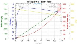
No load current should be 1.8amps for the code 9 at 36Volts, no load rpm should be 350rpm, extrapolated from the BPM datasheet. That would be 1750 motor-rpm @36V, so it should have 48.6KV. From the raw specs, I would say this motor has more torque than the GNG Gen1.
This is what comes out @ 12s lipo / 44.4V, looking gooood
http://www.peakeff.com/GraphKIR.aspx?&v=44.4&kv=48.6&io=1.8&rm=0.07&w=1500&MinThrust=0&MaxThrust=10000&MinMPH=0&MaxMPH=10000&gws=True&apc=False&all=False&title=Bafang+BPM+9T
This is what comes out @ 12s lipo / 44.4V, looking gooood
http://www.peakeff.com/GraphKIR.aspx?&v=44.4&kv=48.6&io=1.8&rm=0.07&w=1500&MinThrust=0&MaxThrust=10000&MinMPH=0&MaxMPH=10000&gws=True&apc=False&all=False&title=Bafang+BPM+9T
Attachments
crossbreak
1 MW
Have some weight figures for you: The BPM adds about 1.2kg to the bike compared to SWXB motor.
The whole SWXB drive unit including the left chain is round about 4.3kg.
My bike is 20.5kg all together (with a bike lock and fenders, light etc ), almost exactly 30kg incl. 1332Wh of battery (2x 666Wh),
with me on it, it weights almost exactly 100kg (99.8 ). The additional weight of the BPM would almost be neglable...
waynebergman
100 kW
Sounds like the pedals unscrewing themselves is now sorted for you crossbreak but back to an earlier comment you made regarding the use of washers for helping the pedals stay in place I got thinking about the norlock washeres I bought from "shinny balls" I use them on my wheel axles but wondering if they also can be had in a smaller diameter to help with the pedal issues. Not sure if they will work for the left hand threads as god as they might for the right hand threaded pedals because of the direction of the wedges built into the washers. Who knows maybe "Nordlock" even makes left hand Nordlock washers. Not sure if this would help but thought I would throw it out there. Thanks again for the awesome thread Crossbreak and sparking the interest ...........wayne
crossbreak
1 MW
Did not yet locktite pedals on my new Hollowtech 2 cranks http://endless-sphere.com/forums/viewtopic.php?f=28&t=47765 , I shall not forget... but even without they did not loosen yet
This Jackshaft solution really works fine... I always have to compare it with commuter bike, which has a 53T chain wheel. The setup I use now on the converted-hub-middrive is a 44/14T input (left side drive) and 20T output sprocket. So it's virtually a 63T chain wheel, which feels a lot better than the real 53T. I only go as fast as I can pedal, and I pedal almost all time, I can recommend this Jackshaft config for everyone who wants to pedal. The only alternative I know would be an expensive and not very lightweight hammerschmidt planetery drive.
This Jackshaft solution really works fine... I always have to compare it with commuter bike, which has a 53T chain wheel. The setup I use now on the converted-hub-middrive is a 44/14T input (left side drive) and 20T output sprocket. So it's virtually a 63T chain wheel, which feels a lot better than the real 53T. I only go as fast as I can pedal, and I pedal almost all time, I can recommend this Jackshaft config for everyone who wants to pedal. The only alternative I know would be an expensive and not very lightweight hammerschmidt planetery drive.
crossbreak
1 MW
I dont see a problem. Locktite works fine, and it can still be unscrewed. It's cheap since you dont need much of it. Perfect for my purpose, I dont bother about this anymore.
spinningmagnets
100 TW
Found an adapter that attaches a 6-hole 44-BCD disc brake onto freewheel threads. the intended purpose is to allow a common wide-axle rear wheel with FW threads to be used as a front wheel and have a disc brake on a bike that did not have one before (of course the caliper mount must also be attached to the fork).
My interest in this is that after this MAC conversion, the motor will be flipped over, with the stock disc brake flange on the right side of the bike. This provides a good place to mount the housing to a bracket, but...how to mount the other side? This $20 adapter should make it easier.
I might not do this, but if I want to...it's nice to have this inexpensive part "in hand".
Seems everyone (3 options) is out of stock except SJS in the UK...edit, I have now received the part in an envelope in my mailbox, and it looks even better in person, I am very pleased with it.
http://www.endless-sphere.com/forums/viewtopic.php?f=28&t=7192&p=697617#p697617
xxxxxxxxxxxxxxxxxxxxxxxxxxxxxxxxxxxx
List of conversion benefits
http://endless-sphere.com/forums/viewtopic.php?f=28&t=45245&start=475#p721375
Bafang specs
http://endless-sphere.com/forums/viewtopic.php?f=28&t=45245&start=475#p722343
crossbreaks graphic
http://endless-sphere.com/forums/download/file.php?id=106021
Whiplash's conversion
http://i116.photobucket.com/albums/o29/fuknmovin/Mobile Uploads/photobucket-1598-1342907343169.jpg
Close-up of mr.electrics BMC / Luna fat-bike
http://endless-sphere.com/forums/viewtopic.php?f=28&t=45245&start=275#p681709
green machine calendar pics of MAC / Luna
http://endless-sphere.com/forums/viewtopic.php?f=28&t=45245&start=425#p696782
John-in-CR's three scooter hub-motor specs:
http://endless-sphere.com/forums/viewtopic.php?f=28&t=48439&p=713337#p713337
crossbreak
1 MW
Thanks for the tip, but this is obsolete. It's too simple to just bore some holes with threads into the hub and it will be much more stiff than using this adapter. Even my thin 1.5mm sheets hold up, I recommend using 2.5mm sheets for mounting the motor. GNG mounts also use 2.5mm sheets and the hold up fine. Except for the motor sprockets, I see nothing that should need any special adapters, this conversion really isn't that hard to do. If I find the time I'll write some howto with more pics in a few mounths. My Bafang BPMs didn't arrive yet, but i'm still very confident that these will be the perfect motors for conversions. #
Hope I can come up with some nice sprocket adapters for both in- and output sprockets.
Hope I can come up with some nice sprocket adapters for both in- and output sprockets.
spinningmagnets
100 TW
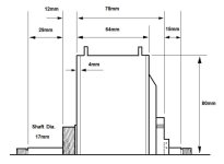
I had some time at work, so drew this. Hope it's helpful, I'm figuring out how I would like a MAC bracket to be shaped. The threads on the axle are 14mm-1.50, 35mm long (older factory blueprints show a 1.25 thread, but all recent MACs seem to have 1.5, which is the same thread as readily available lugnuts for automobiles). Six screws hold on the two side plates each, 12 total, chamfered neck, flush-head Phillips, 4mm X 0.70, threaded portion is 5mm long
I may try to use the disc brake mounting holes as an attachment. They are six holes in a circular pattern, BCD-44mm, 5mm X 0.80, 7mm deep. The disc brake side has a raised ring (for alignment of the brake disc?), and its OD is 33mm, ID is 26mm, and the part of its protrusion from the outer sideplate that is removeable (if you wanted to cut it off) is 7mm. Cutting off 7mm of the central ring would expose a total of 22mm of smooth 17mm-diameter shaft.
When you remove the flat side plate from the FW side, you can see an aluminum collar around the shaft, it is held onto the stator core by six round-head Phillips screws, thread is common 4mm X 0.70
Builders currently experimenting with a MAC crossbreak-style conversion:
crossbreak
bØb
waynebergman
green machine
spinningmagnets
mr.electric
tri-lobe
rodgah
The six side-plate holes look like they are evenly and precisely spaced out in a pattern, but...the even-ness of the drilling pattern is NOT exact. It is vital for this conversion to have the motor re-assemble EXACTLY as it was taken apart, since the heat bridge will attach the flat side plate to the stator. I marked both side-plates with shallow drill-dimples.
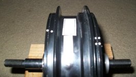
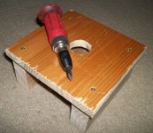
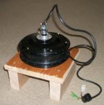
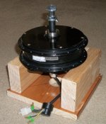
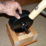
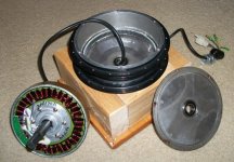
First order of business is to remove the side plate screws (size 4mm X 0.70, 6mm long threads), so I realized it would be much easier with a solid stand for the motor. The space between the 2 X 4 wood side walls (for the planet-gear protrusion on the non-freewheel side) is 4-3/4 inches square (120mm), and the central hole on the base-plate is 2-inches diameter (50mm). The square top-plate is approximately 9-inches square (200+ mm).
I almost stripped the first side-plate Philips-head screw I tried to remove, so I dug out my "impact driver". You hit this tool with a hammer, and it will untwist the screw while at the same time it also pushes down, to prevent the Phillips slots from stripping out. If these threads have thread-locker fluid on them, the impact driver will help quite a bit. The impact driver is one of the few cheap tools I bought at Harbor Freight.
steel sun gear 27T
planet gear bearings 608Z, 8mm ID X 22mm OD X 7mm
Plastic planet gears, 54T
Steel ring gear, 135T
stator diameter (air gap) 5-5/16 inch / 135mm
Stator tooth width 22mm
large central bearing 6205, 25mm X 52mm X 15mm
36 stator teeth
32 magnets, 23mm wide/deep, 14mm following the rim
I may try to use the disc brake mounting holes as an attachment. They are six holes in a circular pattern, BCD-44mm, 5mm X 0.80, 7mm deep. The disc brake side has a raised ring (for alignment of the brake disc?), and its OD is 33mm, ID is 26mm, and the part of its protrusion from the outer sideplate that is removeable (if you wanted to cut it off) is 7mm. Cutting off 7mm of the central ring would expose a total of 22mm of smooth 17mm-diameter shaft.
When you remove the flat side plate from the FW side, you can see an aluminum collar around the shaft, it is held onto the stator core by six round-head Phillips screws, thread is common 4mm X 0.70
Builders currently experimenting with a MAC crossbreak-style conversion:
crossbreak
bØb
waynebergman
green machine
spinningmagnets
mr.electric
tri-lobe
rodgah

The six side-plate holes look like they are evenly and precisely spaced out in a pattern, but...the even-ness of the drilling pattern is NOT exact. It is vital for this conversion to have the motor re-assemble EXACTLY as it was taken apart, since the heat bridge will attach the flat side plate to the stator. I marked both side-plates with shallow drill-dimples.

First order of business is to remove the side plate screws (size 4mm X 0.70, 6mm long threads), so I realized it would be much easier with a solid stand for the motor. The space between the 2 X 4 wood side walls (for the planet-gear protrusion on the non-freewheel side) is 4-3/4 inches square (120mm), and the central hole on the base-plate is 2-inches diameter (50mm). The square top-plate is approximately 9-inches square (200+ mm).
I almost stripped the first side-plate Philips-head screw I tried to remove, so I dug out my "impact driver". You hit this tool with a hammer, and it will untwist the screw while at the same time it also pushes down, to prevent the Phillips slots from stripping out. If these threads have thread-locker fluid on them, the impact driver will help quite a bit. The impact driver is one of the few cheap tools I bought at Harbor Freight.

steel sun gear 27T
planet gear bearings 608Z, 8mm ID X 22mm OD X 7mm
Plastic planet gears, 54T
Steel ring gear, 135T
stator diameter (air gap) 5-5/16 inch / 135mm
Stator tooth width 22mm
large central bearing 6205, 25mm X 52mm X 15mm
36 stator teeth
32 magnets, 23mm wide/deep, 14mm following the rim
spinningmagnets
100 TW
Warning!: the Bafang may prove to be a much better candidate for conversion because the MACs sold previous to June-2013 will have eddy-current losses above 1,000-RPM, and the Bafang has fewer poles, and thus a lower electrical switching frequency, meaning it may run much cooler up to 2,000-RPMs...
edit: if you buy a MAC from cell_man at em3ev.com, he has begun purchasing MACs wholesale with thinner 0.35mm laminations (as opposed to the common 0.50mm), so a NEW MAC (as of June 2013) can be used with higher volts/RPMs. The older version worked well up to 48V, new version should work well at up to 72V/2,000 motor-RPMs.
http://endless-sphere.com/forums/viewtopic.php?f=28&t=45245&p=722413#p722108
xxxxxxxxxxxxxxxxxxxxxxxxxxxxxxxxxxxxxxxxxxxxxxxxxxxxxxxxxxxxxxxxxxxxxxxxxxxxxxxxxxxxxx
edit: I now recommend chopping the wires off, right at the place where they exit the axle, right now at the beginning. After all the experiments have been done, this is the recommended method. Cut the wires where they come out of the axle and leave only a one-inch stub, before you even open the motor up. Keep the cut cable for the hall wires and the stock cable sheath, even if you plan to upgrade the phase wires to a larger diameter.
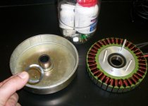
There are several places I mention using a large, empty, and cleaned-out peanut butter jar in which to put the many clips, screws, and washers. They are plastic so they won't break when dropped, a smaller vitamin bottle will fit inside for tiny items you want to isolate, the lid will screw on so it won't pop off by accident, my hand will reach the bottom instead of pouring everything out to get one item, and its clear- so I can see the stored items. Besides all that, who doesn't like peanut butter?
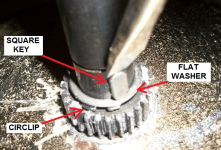
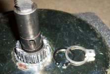
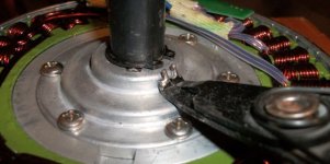
View attachment 10
edit: I now believe it is acceptable (if you want) to cut the wires where they exit the shaft, inside the motor, next to the hall-sensor board. Cut them so as to keep the wire stubs as long as possible between the hall board and the cut, since you will be soldering long wires onto the stubs (either the stock cable-set, or thicker up-graded phase wires)
If I was going to doing this many times, I might make a puller for the aluminum collar, to separate the collar from the shaft while the stator and magnet-rotor are still connected, and that would make this job much easier so there will be less damage to the wires near the hall-sensor board, and the stubs could be a s long as possible. If you used the RED method described above, you will not need a collar-puller to make this job easier, so that the wire insulation is not damaged.
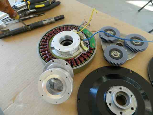
The collar will be thrown away for this conversion, and replaced with an aluminum ring that will act as a stator alignment brace and heat-sink that will bridge the connection from the aluminum stator center, and connect that to the sideplate. This will significantly help heat-shedding. (edit: it may be possible to use the discarded collar as a 17mm-bore sprocket adapter when coupled with two shaft clamps, and a square key slot)
This pic is a drawing of what a collar-puller might look like. The collar is very snug on the shaft. Aluminum will expand more than steel, so if you heat this up with a heat-gun blowing very hot air, I suspect it will come off very easily. edit: it might be cheaper and easier to use three long 1/4-inch all-threaded rods, if they will fit in the M4 holes.
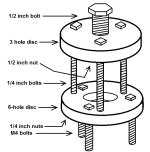
Remove the six M4 screws, and lift the aluminum collar (which is still on the shaft), raise it just enough to slip three M4 nuts under the collar. Attach the puller, and screw the three M4 bolts onto the three M4 nuts under the collar. Actuate the puller to separate the collar from the shaft, and that will free up the cable, which normally makes enough of a bend that it is difficult pull out. The only thing that holds the collar onto the shaft, is a friction-fit.
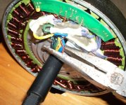
I tried to pull the cable of wires up and out of the hollow axle at this point, and realized that it would be easier to cut the cable where the wires exit the hollow axle inside the motor, near the hall-board (you only lose 5 inches of cable that way), and then resolder the wires after the motor is completely apart.
I also tried to pull on ALL of the wires at once, which was causing much damage to the wires' insulation. So...I tried something different; After cutting the wires near the axle end, I sprayed WD40 into the wires as a lubricant, and then pulled out one single phase wire, then a second phase wire, and then the rest slipped out easily. (edit: after finishing all the experiments, this is the most recommended method). Leave the 5 hall wires to pull out of the axle LAST, because they are the most fragile.
For getting the motor apart quickly, cutting the wire-bundle next to the hall-board is best, but...for making the soldering easier during re-assembly(and upgrading the phase wires), cutting the wire-bundle outside the motor at the axle-end is best.
If you are willing to take a risk, it is fairly easy to cut the bundle of wires here: right at the place where they come out of the axle, right next to the collar. If you do this, it will make the phase/hall-wires very short (roughly 3-inches?), but...if you are confident in your soldering skills, you can make a good connection to the new hall-wires without getting the length of the wires so hot that: it might damage the hall-sensor board. If your soldering DOES damage the hall-sensor board, don't panic, the high pole-count MAC runs well in sensorless mode.
edit: I am happy to report that the wire soldering to 3-inch stubs went well. I have a 100W soldering iron with a lot of mass at the fat tip, so the soldering went very fast. The wires were only very warm just one inch away from the soldering. I still prefer the highlighted method above, because soldering to 7-inch long stubs is much easier than soldering to 3-inch stubs, which is awkward when trying to prevent damage to the stator.
If you take the option of cutting the cable in this place (short phase wire stubs), you don't need a collar-puller, and the collar/shaft assembly will slip out easily at this point. Once the axle and the attached collar are removed from the stator, they can be put in a vice to separate them from each other.
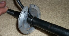
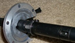
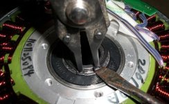
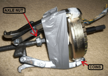
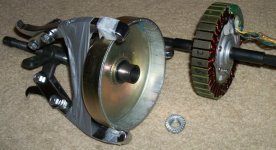
At this point (after the cable is cut and the wires inside the hollow axle are removed), you must re-install the axle and the collar, and re-insert the six 4mm screws that hold the collar to the stator-core. Tape some coins inside each jaw of the pulley-puller, so it will grab only the magnet-ring edge. If you accidentally grab both the magnet-rotor and the stator because the jaws reach-in too deep, the stator can be damaged when you tighten the 3-arm puller.
I found it helps to wrap the three puller-arms with duct tape, because one of them will slip off at just the wrong moment when trying to tighten it. I also put one of the axle-nuts on the end of the axle (just a few threads) so the pullers' central shaft will not slip off when it's tightened. Just when you think the steel stator has escaped the attraction of the magnet-ring...DO NOT GET YOUR FINGERS BETWEEN THE MAGNETS AND THE STEEL STATOR! These neodymium magnets are VERY strong. When the stator has pulled completely out of the magnet-ring, place two thin wood strips between them (perhaps free paint stirring sticks from the hardware store?), and then remove the axle nut in the back.
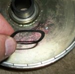
View attachment 1
edit: if you buy a MAC from cell_man at em3ev.com, he has begun purchasing MACs wholesale with thinner 0.35mm laminations (as opposed to the common 0.50mm), so a NEW MAC (as of June 2013) can be used with higher volts/RPMs. The older version worked well up to 48V, new version should work well at up to 72V/2,000 motor-RPMs.
We now have a new and improved version of the MAC motor as well as the standard MAC motor. Our new version MAC now includes the same mods as before, both the upgraded phase wires and LM35 temp sensor, but now also includes an upgraded stator which offers improved efficiency and the ability to operate at higher speeds than were possible with the standard stator.
edit: paul has responded, and the new MAC laminations are definitely the 0.35mm thickness.
http://endless-sphere.com/forums/viewtopic.php?f=28&t=45245&p=722413#p722108
xxxxxxxxxxxxxxxxxxxxxxxxxxxxxxxxxxxxxxxxxxxxxxxxxxxxxxxxxxxxxxxxxxxxxxxxxxxxxxxxxxxxxx
edit: I now recommend chopping the wires off, right at the place where they exit the axle, right now at the beginning. After all the experiments have been done, this is the recommended method. Cut the wires where they come out of the axle and leave only a one-inch stub, before you even open the motor up. Keep the cut cable for the hall wires and the stock cable sheath, even if you plan to upgrade the phase wires to a larger diameter.
There are several places I mention using a large, empty, and cleaned-out peanut butter jar in which to put the many clips, screws, and washers. They are plastic so they won't break when dropped, a smaller vitamin bottle will fit inside for tiny items you want to isolate, the lid will screw on so it won't pop off by accident, my hand will reach the bottom instead of pouring everything out to get one item, and its clear- so I can see the stored items. Besides all that, who doesn't like peanut butter?


View attachment 10
edit: I now believe it is acceptable (if you want) to cut the wires where they exit the shaft, inside the motor, next to the hall-sensor board. Cut them so as to keep the wire stubs as long as possible between the hall board and the cut, since you will be soldering long wires onto the stubs (either the stock cable-set, or thicker up-graded phase wires)
If I was going to doing this many times, I might make a puller for the aluminum collar, to separate the collar from the shaft while the stator and magnet-rotor are still connected, and that would make this job much easier so there will be less damage to the wires near the hall-sensor board, and the stubs could be a s long as possible. If you used the RED method described above, you will not need a collar-puller to make this job easier, so that the wire insulation is not damaged.
The collar will be thrown away for this conversion, and replaced with an aluminum ring that will act as a stator alignment brace and heat-sink that will bridge the connection from the aluminum stator center, and connect that to the sideplate. This will significantly help heat-shedding. (edit: it may be possible to use the discarded collar as a 17mm-bore sprocket adapter when coupled with two shaft clamps, and a square key slot)
This pic is a drawing of what a collar-puller might look like. The collar is very snug on the shaft. Aluminum will expand more than steel, so if you heat this up with a heat-gun blowing very hot air, I suspect it will come off very easily. edit: it might be cheaper and easier to use three long 1/4-inch all-threaded rods, if they will fit in the M4 holes.

Remove the six M4 screws, and lift the aluminum collar (which is still on the shaft), raise it just enough to slip three M4 nuts under the collar. Attach the puller, and screw the three M4 bolts onto the three M4 nuts under the collar. Actuate the puller to separate the collar from the shaft, and that will free up the cable, which normally makes enough of a bend that it is difficult pull out. The only thing that holds the collar onto the shaft, is a friction-fit.
I tried to pull the cable of wires up and out of the hollow axle at this point, and realized that it would be easier to cut the cable where the wires exit the hollow axle inside the motor, near the hall-board (you only lose 5 inches of cable that way), and then resolder the wires after the motor is completely apart.
I also tried to pull on ALL of the wires at once, which was causing much damage to the wires' insulation. So...I tried something different; After cutting the wires near the axle end, I sprayed WD40 into the wires as a lubricant, and then pulled out one single phase wire, then a second phase wire, and then the rest slipped out easily. (edit: after finishing all the experiments, this is the most recommended method). Leave the 5 hall wires to pull out of the axle LAST, because they are the most fragile.
For getting the motor apart quickly, cutting the wire-bundle next to the hall-board is best, but...for making the soldering easier during re-assembly(and upgrading the phase wires), cutting the wire-bundle outside the motor at the axle-end is best.
If you are willing to take a risk, it is fairly easy to cut the bundle of wires here: right at the place where they come out of the axle, right next to the collar. If you do this, it will make the phase/hall-wires very short (roughly 3-inches?), but...if you are confident in your soldering skills, you can make a good connection to the new hall-wires without getting the length of the wires so hot that: it might damage the hall-sensor board. If your soldering DOES damage the hall-sensor board, don't panic, the high pole-count MAC runs well in sensorless mode.
edit: I am happy to report that the wire soldering to 3-inch stubs went well. I have a 100W soldering iron with a lot of mass at the fat tip, so the soldering went very fast. The wires were only very warm just one inch away from the soldering. I still prefer the highlighted method above, because soldering to 7-inch long stubs is much easier than soldering to 3-inch stubs, which is awkward when trying to prevent damage to the stator.
If you take the option of cutting the cable in this place (short phase wire stubs), you don't need a collar-puller, and the collar/shaft assembly will slip out easily at this point. Once the axle and the attached collar are removed from the stator, they can be put in a vice to separate them from each other.


At this point (after the cable is cut and the wires inside the hollow axle are removed), you must re-install the axle and the collar, and re-insert the six 4mm screws that hold the collar to the stator-core. Tape some coins inside each jaw of the pulley-puller, so it will grab only the magnet-ring edge. If you accidentally grab both the magnet-rotor and the stator because the jaws reach-in too deep, the stator can be damaged when you tighten the 3-arm puller.
I found it helps to wrap the three puller-arms with duct tape, because one of them will slip off at just the wrong moment when trying to tighten it. I also put one of the axle-nuts on the end of the axle (just a few threads) so the pullers' central shaft will not slip off when it's tightened. Just when you think the steel stator has escaped the attraction of the magnet-ring...DO NOT GET YOUR FINGERS BETWEEN THE MAGNETS AND THE STEEL STATOR! These neodymium magnets are VERY strong. When the stator has pulled completely out of the magnet-ring, place two thin wood strips between them (perhaps free paint stirring sticks from the hardware store?), and then remove the axle nut in the back.


View attachment 1
spinningmagnets
100 TW
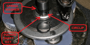
The part that makes this a conversion from a shell-drive into a shaft-drive is that: the stator is "unpinned" from the axle-- by removing the square shaft key and also the aluminum shaft-to-stator collar.
Then...the stator must be solidly attached to the flat sideplate. If the new stator-brace that attaches the stator to the flat side-plate is made from thick aluminum, it will transfer heat from the stator core to the sideplate, and then to the entire motor-shell. This optional heat-transfer is a major benefit.
For the axle to turn in the same direction as the rear wheel of the bicycle (after this conversion), you must flip over the motor so that the flat side of the motor housing will now be on the left. Also, the long part of the axle-shaft will now be on the left.
Do not worry about keeping the stator centered in the magnetic rotor. With the side plate off, you can feel a small amount of axle "wiggle" due to the one side plate axle bearing being removed with that sideplate. When the flat sideplate is re-installed, the two axle bearings and the large central stator bearing will keep the stator and magnet-ring perfectly aligned.
To describe this in another way, the stator center and the magnet-rotor center are connected to each other by the large central bearing. This stator/rotor "assembly" is attached to the flat sideplate by the bolted-on heat-bridge on the housings' flat-plate side. And then, on the other side, it is supported by the central sun-gear of the magnet-rotor being suspended in the center of the three large planet-gears.
The shaft and planet-gear carrier-disc "assembly" will continue to use their stock square shaft-key and snug-fit to connect to each other. This assembly is supported by the outer ring-gear, which is firmly attached to the left side-plate. The two side-plate bearings will support the shaft, and will hold the alignment and centering of this assembly.
[insert pics of bikini girls on Ebikes, yada yada yada]
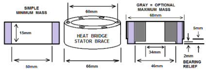
There are several ways to do this, and no single way to shape the heat-bridge ring. My plan is to make precise measurements to form the heat-bridge ring, but to make it it slightly too tall for the side-plate to seat completely. Once the sideplate screws are merely finger-snug and evenly inserted all the way around (do not make the assembly so tight that the three internal spring washers are completely compressed), I will make a final measurement of the side plate air-gap, and I will then remove the heat-bridge ring and shave it to the final dimension. This will account for minor manufacturing variations between one motor and a different one. The measurements I'm reading: are 15mm for the heat bridge width (but yours might be 14.5mm or 15.5mm). Proceed at your own risk, and with caution.
Below are rough estimates of what a heat-bridge/stator-brace would look like for a MAC, a BMC, and a Bafang.
edit: waynebergman has reported that the stator-recess that the heat-bridge sits in on his MAC is 67mm diameter (instead of 66mm, like mine), so be aware that assembly-line accuracy varies from one motor to another.
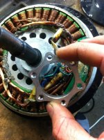
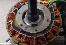
[insert video of Lukes Deathbike riding through a ring of fire on a wheelie while Luke is firing a submachine gun, yada yada yada]
xxxxxxxxxxxxxxxxxxxxxxxxxxxxxxxxxxxxxxxxxxxxxxxxxxxxxxxxxxxx
There are 3 options for connecting the heat bridge to the stator and side-plate.
1) Long M4 bolts pass from outside the 4mm thick side-plate, through the 15mm heat-bridge and thread into the stock 11mm-deep stator-core threaded holes (25-28mm long bolts?).
2) The heat-bridge is permanently bonded to the stator-core, and 14-16mm length bolts attach the side-plate to the heat-bridge.
3) The heat bridge is permanently bonded to the inside of the flat side-plate, and 18-22mm length bolts hold the stator onto the heat-bridge.
xxxxxxxxxxxxxxxxxxxxxxxxxxxxxxxxxxxxxxxxxxxxxxxxxxxxxxxxxx
Option 1
Carefully make a heat-bridge using the supplied dimensions, set it on the stator and verify the bolts will pass through the full-length 4mm (4.5mm?) diameter holes, and screw into the stock six stator-core threaded holes (checking for alignment and exact placement of holes). Make three short headless M4 studs to screw into the stator threads (ie, cut the heads off of three short M4 bolts), and they will be used to align the heat-bridge when you assemble the motor, and then they will mark where to drill the holes in the side-plate.
Screw-in the three studs, and set the heat-bridge onto them. The stud length should barely insert into the heat-bridge holes, they are only for alignment. Put coil springs from three retractable pens into three of the holes in the heat-bridge. Take three additional headless M4 bolts and set them on the springs so they protrude up.
Prepare to line up the side plate with the motor face-up (remember the drill dimple-spots?). Put some wet dye on the three protruding sprung stud tips, and assemble the side plate (I have used machinists' blue dye for similar jobs). You can assemble the side plate exactly and quickly if you set two 3mm drill bits in two of the rim-holes to guide you when you press it down. The three studs will mark three of the places you need to drill. You can then dis-assemble, drill those holes that have their places marked (using a clamped-on heat-bridge as a guide?), and then bolt the heat-bridge to those three holes. Then you can drill the other three holes through the heat-bridge (or at the very least, mark their spots, if the drill bit is too short to go all the way through).
An alternative to using dye; another way is to mark the spot the studs will hit on the inside of the side-plate with black felt marker (for visual contrast), and sharpen the stud tips on a grinder so that when the side-plate is pressed down, the sharp points will make a tiny-shiny ding in the black spot on the aluminum. Test-fit the six bolts, and If they don't line up correctly, you can rotate the heat bridge and try one more time, but...too many holes will weaken the side-plate.
xxxxxxxxxxxxxxxxxxxxxxxxxxxxxxxxxxxxxxxxxxxxxxxxxxxxxxxxxx
Option 2
Temporarily bond the heat-bridge ring to the central aluminum stator core (silicone?), once its final precise size and shape are determined. Use the previously described method for making the 6 holes in the side-plate (as in option 1). Bolt the heat bridge to the side-plate, but only finger-tight.
Sand and clean the stator and heat-bridge at the places they will mate. File off the sharp outer-edge where the heat-bridge will insert. Smear some DP-420 between the stator and heat-bridge. Quickly assemble all the parts, and tighten the six bolts, so everything will be in perfect alignment while the epoxy dries.
[insert pic of Thud fixing the space station with only duct tape and baling wire while the college-educated astronauts are befuddled in the background, yada yada yada]
xxxxxxxxxxxxxxxxxxxxxxxxxxxxxxxxxxxxxxxxxxxxxxxxxxxxxxxxxxx
OPTION 3
A third option is to take the aluminum stator-core, and take the six threaded holes in it...and drill them all the way through. Then use six bolts to attach the heat bridge to the stator...from the back side:
Drill the six holes on the stator-core to all the way through, entering from the threaded end, using a 3.5mm drill bit as an M4 pilot. Then, temporarily bond the heat-bridge to the stator with a weak adhesive (silicone?). Drill through the stator from the back into the heat bridge, to 3.5mm dia in all six places. If the bit is too short, you only need a shallow hole on the heat-bridge for spot-location. http://www.mcmaster.com/#standard-drill-bits/=m7ozl2
Mark the heat-bridge and stator with a chisel/drill-dimple on both of them, so they can be assembled in the same orientation. This is to account for the minor mis-alignment of precise hole locations. Remove the heat-bridge and drill the six pilot-holes in the heat-bridge as deep as you can. Flip the heat-bridge over, and drill each hole to a diameter of 5mm, but...just a small depth, I mean "just enough" depth that it connects to the pilot hole, perhaps a maximum depth of 5mm. Tap M4 threads into these six 3.5mm holes. The 5mm recesses should face the flat side-plate.
Be cautious and slow, test your thread-tapping skills on a piece of scrap aluminum first, If you break-off the small tap in the heat bridge hole, it will be a nightmare to fix, and you would still have to buy a new tap to thread the other 5 holes. Use thread-cutting lubricant, and go one turn in, then remove the tap to clean the cuttings. Then 2-turns in, remove to clean, 3-turns / clean, etc. If you are tapping large threads into aluminum, it is very forgiving. However, small threads in small diameter holes will require a great deal of caution.
The tap will be high-carbon steel, which has a very hard skin to hold its sharp edge, but they are brittle, and the small ones break easily. Don't be lazy, take the extra time, and the tap will last many years of cutting soft aluminum.
After the heat-bridge holes are threaded, you can drill out the six stator-holes to 4mm, then drill a shallow recess on the back end of the hole so the bolt heads will be flush (perhaps 6mm deep?). The stator core is 16mm thick at the center. I recommend six "socket head cap screws". If the bolt-head recess is 8mm dia and 6mm deep, the remaining length is 10mm of stator-core, plus an adequate penetration into the heat-bridge threaded holes (8mm minimum), so look for 18-22mm length bolts. http://www.homedepot.com/p/M4-7-x-2...Cap-Screw-2-Pack-08368/203538869#.UWBJaKJpzNs
Clean everything up, bolt the heat-bridge onto the stator-core, assemble the ENTIRE motor (except the flat side-plate) to ensure all the parts will align themselves to each other when the epoxy dries.
We must now permanently bond the other end of the heat-bridge to the flat side-plate. To prevent DP-420 from squeezing out into a big drip, and damaging something, smear grease on everything inside the heat bridge, and then tape off everything for two inches around the outside of the heat bridge. Sand and clean the exposed edge of the heat-bridge, and also the inside of the flat side-plate. This will ensure the mating surfaces will be rough and have no oil or grease on them, and this will make a very strong bond.
Smear some DP-420 onto the edge of the heat-bridge, and assemble the flat side plate (make sure the two dimples are aligned first). Snug up all six side plate screws and set the motor flat-side down, with the axle vertical. Wait 24-hours, and then disassemble for a quick inspection, and to clean off any hard epoxy drips. If it's all good, leave the plate off and proceed to the wrap-up...
xxxxxxxxxxxxxxxxxxxxxxxxxxxxxxxxxxxxxxxxxxxxxxxxxxxxxxxxxx
Let's wrap it up!
[insert pic of dogman finishing a diesel/electric hybrid that runs off of soybean oil he grows himself, made from near-free castaways, yada yada yada]
Estimate the best place to put the new large side-plate hole in the flat side of the motor for the wires to exit the motor. Drill an XXX hole in the flat sideplate (1/2-inch dia? 3/4-inch?) for the new fatter phase-wires, hall-wires, and possibly wires for a temp probe. I am considering epoxying a 1/2-inch ID PVC 90-degree elbow onto the hole, and having the wires exiting the flat side-plate, and pointed down to resist rain-drips and puddle-splashes.
Temp sensor that’s too cool not to share
http://endless-sphere.com/forums/viewtopic.php?f=1&t=25502
Installing a temp sensor in a hub motor
https://sites.google.com/site/shelbyelectro/motors/mods/installing-a-temp-sensor-in-a-hub-motor
This is the perfect time to run fatter phase-wires to the motor (hall wires do not need to be upgraded). Although,...in the new configuration...it's now easy to do anytime if you decide you want that later. The motor should run much cooler when you are able to keep it in the upper RPMs (as a non-hub with gears), so the stock wires will likely be adequate at twice the performance, compared to what you had before, with the hub in the normal rear-wheel location.
Trim the mangled stock wire stubs, strip the ends, and solder the new wires onto them. Use heat-shrink insulation on each individual wire, and then put a large diameter section of heat-shrink around the entire bundle. Below is the butt-splice method shown to me by Amberwolf, and it is the best method I have found by far.
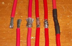
The magnet ring is centered by a friction fit of the OD of the central tube section into the ID of the large main central bearing, (on the stator side). On the other side, the central sun-gear (which is solidly attached to the magnet-ring shell) is suspended and floating in-between the three planet gears. As you may recall, the planet gear-carrier is pinned to the shaft with a circlip and square-key, and this assembly is aligned-by and rides-on the two side-plate bearings.
The shaft does not touch the stator or magnet-ring central-tube at all (this is a concern because the stator is (of course) stationary, and the shaft will now be spinning rapidly). The central hole in the center tube of the magnet-ring is 19mm ID, and the shaft at that point is 17mm OD.
When re-assembling, smear a small amount of NON-conductive thermal paste on every NON-epoxied end of the heat bridge. Here are several selections:
_$8 / 3g tube, Xigmatek PTI-G3606,
_$8 / 3g tube, Tuniq TX-2
_$9 / 4g tube, Arctic Cooling MX-2 Thermal Compound,
Here is a pic comparing the stock 4mm thick flat sideplate, and the "green machine" conversion sideplate with integrated heat-bridge/stator-brace which is 6mm thick in its field and 11mm thick at the reinforced rim.
View attachment 3
xxxxxxxxxxxxxxxxxxxxxxxxxxxxxxxxxxxxxxxxxxxxxxxxxx
For where the wires exit the flat side-plate, one option is to use a $2 plastic conduit elbow, listed as a "water-tight twist-in, 1/2-inch" (http://www.mcmaster.com/#standard-electrical-conduit/=m9ztvz). The 1/2-inch bore will easily fit three 10-AWG silicone wires along with the stock tiny five hall wires (also readily available in 3/4-inch. The elbow will be pointed down, and the wires will make a U-turn up to form a "drip loop", also the opening will have some silicone sealant in it to add water-proofing that will be easy to remove if needed.
You may need to trim the threads down to a 4mm depth, so they do not protrude into the interior of the motor when you epoxy the elbow onto the side-plate hole. The supplied thin metal nut may not be thin enough (roughly 4mm) to clear the rotor edge or stator (I will check for this when I re-assemble).

Here is a pic of mr.electrics BMC conversion with the wires exiting the side plate.
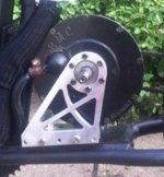
Another alternative would be to use a round file to make 4 notches (three 12-ga phase wires, and one heat-shrunk bundle of 5 hall-wires) on the edge of the aluminum housing just below where the flat side plate attaches. A dab of silicone sealant on each notch would keep out moisture, and I would recommend these openings be on the lower part of the motor position. This would also allow the wires to exit the case radially (like spokes), instead of protruding from the side-plate. Add a section of large heat-shrink at the point the wire-bundle exits the side-plate and make sure the opening(s) are deburred. A years worth of minor vibration when riding can wear through the wire insulation and short the wires, and filling the exit hole(s) with silicone should help a lot to prevent that.
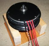
Then...the stator must be solidly attached to the flat sideplate. If the new stator-brace that attaches the stator to the flat side-plate is made from thick aluminum, it will transfer heat from the stator core to the sideplate, and then to the entire motor-shell. This optional heat-transfer is a major benefit.
For the axle to turn in the same direction as the rear wheel of the bicycle (after this conversion), you must flip over the motor so that the flat side of the motor housing will now be on the left. Also, the long part of the axle-shaft will now be on the left.
Do not worry about keeping the stator centered in the magnetic rotor. With the side plate off, you can feel a small amount of axle "wiggle" due to the one side plate axle bearing being removed with that sideplate. When the flat sideplate is re-installed, the two axle bearings and the large central stator bearing will keep the stator and magnet-ring perfectly aligned.
To describe this in another way, the stator center and the magnet-rotor center are connected to each other by the large central bearing. This stator/rotor "assembly" is attached to the flat sideplate by the bolted-on heat-bridge on the housings' flat-plate side. And then, on the other side, it is supported by the central sun-gear of the magnet-rotor being suspended in the center of the three large planet-gears.
The shaft and planet-gear carrier-disc "assembly" will continue to use their stock square shaft-key and snug-fit to connect to each other. This assembly is supported by the outer ring-gear, which is firmly attached to the left side-plate. The two side-plate bearings will support the shaft, and will hold the alignment and centering of this assembly.
[insert pics of bikini girls on Ebikes, yada yada yada]
There are several ways to do this, and no single way to shape the heat-bridge ring. My plan is to make precise measurements to form the heat-bridge ring, but to make it it slightly too tall for the side-plate to seat completely. Once the sideplate screws are merely finger-snug and evenly inserted all the way around (do not make the assembly so tight that the three internal spring washers are completely compressed), I will make a final measurement of the side plate air-gap, and I will then remove the heat-bridge ring and shave it to the final dimension. This will account for minor manufacturing variations between one motor and a different one. The measurements I'm reading: are 15mm for the heat bridge width (but yours might be 14.5mm or 15.5mm). Proceed at your own risk, and with caution.
Below are rough estimates of what a heat-bridge/stator-brace would look like for a MAC, a BMC, and a Bafang.
edit: waynebergman has reported that the stator-recess that the heat-bridge sits in on his MAC is 67mm diameter (instead of 66mm, like mine), so be aware that assembly-line accuracy varies from one motor to another.


[insert video of Lukes Deathbike riding through a ring of fire on a wheelie while Luke is firing a submachine gun, yada yada yada]
xxxxxxxxxxxxxxxxxxxxxxxxxxxxxxxxxxxxxxxxxxxxxxxxxxxxxxxxxxxx
There are 3 options for connecting the heat bridge to the stator and side-plate.
1) Long M4 bolts pass from outside the 4mm thick side-plate, through the 15mm heat-bridge and thread into the stock 11mm-deep stator-core threaded holes (25-28mm long bolts?).
2) The heat-bridge is permanently bonded to the stator-core, and 14-16mm length bolts attach the side-plate to the heat-bridge.
3) The heat bridge is permanently bonded to the inside of the flat side-plate, and 18-22mm length bolts hold the stator onto the heat-bridge.
xxxxxxxxxxxxxxxxxxxxxxxxxxxxxxxxxxxxxxxxxxxxxxxxxxxxxxxxxx
Option 1
Carefully make a heat-bridge using the supplied dimensions, set it on the stator and verify the bolts will pass through the full-length 4mm (4.5mm?) diameter holes, and screw into the stock six stator-core threaded holes (checking for alignment and exact placement of holes). Make three short headless M4 studs to screw into the stator threads (ie, cut the heads off of three short M4 bolts), and they will be used to align the heat-bridge when you assemble the motor, and then they will mark where to drill the holes in the side-plate.
Screw-in the three studs, and set the heat-bridge onto them. The stud length should barely insert into the heat-bridge holes, they are only for alignment. Put coil springs from three retractable pens into three of the holes in the heat-bridge. Take three additional headless M4 bolts and set them on the springs so they protrude up.
Prepare to line up the side plate with the motor face-up (remember the drill dimple-spots?). Put some wet dye on the three protruding sprung stud tips, and assemble the side plate (I have used machinists' blue dye for similar jobs). You can assemble the side plate exactly and quickly if you set two 3mm drill bits in two of the rim-holes to guide you when you press it down. The three studs will mark three of the places you need to drill. You can then dis-assemble, drill those holes that have their places marked (using a clamped-on heat-bridge as a guide?), and then bolt the heat-bridge to those three holes. Then you can drill the other three holes through the heat-bridge (or at the very least, mark their spots, if the drill bit is too short to go all the way through).
An alternative to using dye; another way is to mark the spot the studs will hit on the inside of the side-plate with black felt marker (for visual contrast), and sharpen the stud tips on a grinder so that when the side-plate is pressed down, the sharp points will make a tiny-shiny ding in the black spot on the aluminum. Test-fit the six bolts, and If they don't line up correctly, you can rotate the heat bridge and try one more time, but...too many holes will weaken the side-plate.
xxxxxxxxxxxxxxxxxxxxxxxxxxxxxxxxxxxxxxxxxxxxxxxxxxxxxxxxxx
Option 2
Temporarily bond the heat-bridge ring to the central aluminum stator core (silicone?), once its final precise size and shape are determined. Use the previously described method for making the 6 holes in the side-plate (as in option 1). Bolt the heat bridge to the side-plate, but only finger-tight.
Sand and clean the stator and heat-bridge at the places they will mate. File off the sharp outer-edge where the heat-bridge will insert. Smear some DP-420 between the stator and heat-bridge. Quickly assemble all the parts, and tighten the six bolts, so everything will be in perfect alignment while the epoxy dries.
[insert pic of Thud fixing the space station with only duct tape and baling wire while the college-educated astronauts are befuddled in the background, yada yada yada]
xxxxxxxxxxxxxxxxxxxxxxxxxxxxxxxxxxxxxxxxxxxxxxxxxxxxxxxxxxx
OPTION 3
A third option is to take the aluminum stator-core, and take the six threaded holes in it...and drill them all the way through. Then use six bolts to attach the heat bridge to the stator...from the back side:
Drill the six holes on the stator-core to all the way through, entering from the threaded end, using a 3.5mm drill bit as an M4 pilot. Then, temporarily bond the heat-bridge to the stator with a weak adhesive (silicone?). Drill through the stator from the back into the heat bridge, to 3.5mm dia in all six places. If the bit is too short, you only need a shallow hole on the heat-bridge for spot-location. http://www.mcmaster.com/#standard-drill-bits/=m7ozl2
Mark the heat-bridge and stator with a chisel/drill-dimple on both of them, so they can be assembled in the same orientation. This is to account for the minor mis-alignment of precise hole locations. Remove the heat-bridge and drill the six pilot-holes in the heat-bridge as deep as you can. Flip the heat-bridge over, and drill each hole to a diameter of 5mm, but...just a small depth, I mean "just enough" depth that it connects to the pilot hole, perhaps a maximum depth of 5mm. Tap M4 threads into these six 3.5mm holes. The 5mm recesses should face the flat side-plate.
Be cautious and slow, test your thread-tapping skills on a piece of scrap aluminum first, If you break-off the small tap in the heat bridge hole, it will be a nightmare to fix, and you would still have to buy a new tap to thread the other 5 holes. Use thread-cutting lubricant, and go one turn in, then remove the tap to clean the cuttings. Then 2-turns in, remove to clean, 3-turns / clean, etc. If you are tapping large threads into aluminum, it is very forgiving. However, small threads in small diameter holes will require a great deal of caution.
The tap will be high-carbon steel, which has a very hard skin to hold its sharp edge, but they are brittle, and the small ones break easily. Don't be lazy, take the extra time, and the tap will last many years of cutting soft aluminum.
After the heat-bridge holes are threaded, you can drill out the six stator-holes to 4mm, then drill a shallow recess on the back end of the hole so the bolt heads will be flush (perhaps 6mm deep?). The stator core is 16mm thick at the center. I recommend six "socket head cap screws". If the bolt-head recess is 8mm dia and 6mm deep, the remaining length is 10mm of stator-core, plus an adequate penetration into the heat-bridge threaded holes (8mm minimum), so look for 18-22mm length bolts. http://www.homedepot.com/p/M4-7-x-2...Cap-Screw-2-Pack-08368/203538869#.UWBJaKJpzNs
Clean everything up, bolt the heat-bridge onto the stator-core, assemble the ENTIRE motor (except the flat side-plate) to ensure all the parts will align themselves to each other when the epoxy dries.
We must now permanently bond the other end of the heat-bridge to the flat side-plate. To prevent DP-420 from squeezing out into a big drip, and damaging something, smear grease on everything inside the heat bridge, and then tape off everything for two inches around the outside of the heat bridge. Sand and clean the exposed edge of the heat-bridge, and also the inside of the flat side-plate. This will ensure the mating surfaces will be rough and have no oil or grease on them, and this will make a very strong bond.
Smear some DP-420 onto the edge of the heat-bridge, and assemble the flat side plate (make sure the two dimples are aligned first). Snug up all six side plate screws and set the motor flat-side down, with the axle vertical. Wait 24-hours, and then disassemble for a quick inspection, and to clean off any hard epoxy drips. If it's all good, leave the plate off and proceed to the wrap-up...
xxxxxxxxxxxxxxxxxxxxxxxxxxxxxxxxxxxxxxxxxxxxxxxxxxxxxxxxxx
Let's wrap it up!
[insert pic of dogman finishing a diesel/electric hybrid that runs off of soybean oil he grows himself, made from near-free castaways, yada yada yada]
Estimate the best place to put the new large side-plate hole in the flat side of the motor for the wires to exit the motor. Drill an XXX hole in the flat sideplate (1/2-inch dia? 3/4-inch?) for the new fatter phase-wires, hall-wires, and possibly wires for a temp probe. I am considering epoxying a 1/2-inch ID PVC 90-degree elbow onto the hole, and having the wires exiting the flat side-plate, and pointed down to resist rain-drips and puddle-splashes.
Temp sensor that’s too cool not to share
http://endless-sphere.com/forums/viewtopic.php?f=1&t=25502
Installing a temp sensor in a hub motor
https://sites.google.com/site/shelbyelectro/motors/mods/installing-a-temp-sensor-in-a-hub-motor
This is the perfect time to run fatter phase-wires to the motor (hall wires do not need to be upgraded). Although,...in the new configuration...it's now easy to do anytime if you decide you want that later. The motor should run much cooler when you are able to keep it in the upper RPMs (as a non-hub with gears), so the stock wires will likely be adequate at twice the performance, compared to what you had before, with the hub in the normal rear-wheel location.
Trim the mangled stock wire stubs, strip the ends, and solder the new wires onto them. Use heat-shrink insulation on each individual wire, and then put a large diameter section of heat-shrink around the entire bundle. Below is the butt-splice method shown to me by Amberwolf, and it is the best method I have found by far.

The magnet ring is centered by a friction fit of the OD of the central tube section into the ID of the large main central bearing, (on the stator side). On the other side, the central sun-gear (which is solidly attached to the magnet-ring shell) is suspended and floating in-between the three planet gears. As you may recall, the planet gear-carrier is pinned to the shaft with a circlip and square-key, and this assembly is aligned-by and rides-on the two side-plate bearings.
The shaft does not touch the stator or magnet-ring central-tube at all (this is a concern because the stator is (of course) stationary, and the shaft will now be spinning rapidly). The central hole in the center tube of the magnet-ring is 19mm ID, and the shaft at that point is 17mm OD.
When re-assembling, smear a small amount of NON-conductive thermal paste on every NON-epoxied end of the heat bridge. Here are several selections:
_$8 / 3g tube, Xigmatek PTI-G3606,
_$8 / 3g tube, Tuniq TX-2
_$9 / 4g tube, Arctic Cooling MX-2 Thermal Compound,
Here is a pic comparing the stock 4mm thick flat sideplate, and the "green machine" conversion sideplate with integrated heat-bridge/stator-brace which is 6mm thick in its field and 11mm thick at the reinforced rim.
View attachment 3
xxxxxxxxxxxxxxxxxxxxxxxxxxxxxxxxxxxxxxxxxxxxxxxxxx
For where the wires exit the flat side-plate, one option is to use a $2 plastic conduit elbow, listed as a "water-tight twist-in, 1/2-inch" (http://www.mcmaster.com/#standard-electrical-conduit/=m9ztvz). The 1/2-inch bore will easily fit three 10-AWG silicone wires along with the stock tiny five hall wires (also readily available in 3/4-inch. The elbow will be pointed down, and the wires will make a U-turn up to form a "drip loop", also the opening will have some silicone sealant in it to add water-proofing that will be easy to remove if needed.
You may need to trim the threads down to a 4mm depth, so they do not protrude into the interior of the motor when you epoxy the elbow onto the side-plate hole. The supplied thin metal nut may not be thin enough (roughly 4mm) to clear the rotor edge or stator (I will check for this when I re-assemble).

Here is a pic of mr.electrics BMC conversion with the wires exiting the side plate.

Another alternative would be to use a round file to make 4 notches (three 12-ga phase wires, and one heat-shrunk bundle of 5 hall-wires) on the edge of the aluminum housing just below where the flat side plate attaches. A dab of silicone sealant on each notch would keep out moisture, and I would recommend these openings be on the lower part of the motor position. This would also allow the wires to exit the case radially (like spokes), instead of protruding from the side-plate. Add a section of large heat-shrink at the point the wire-bundle exits the side-plate and make sure the opening(s) are deburred. A years worth of minor vibration when riding can wear through the wire insulation and short the wires, and filling the exit hole(s) with silicone should help a lot to prevent that.

spinningmagnets
100 TW
I decided to do something that isn't really necessary. The six M4-threaded holes in the stator core are about 7mm deep (roughly ten turns on the bolt before they bottom-out), I want to drill them all the way through and tap threads into the entire length.
Also, even if you felt the 7mm deep threads are adequate, but you wanted full bolt penetration, you can drill out these holes from the other side to a diameter of 5mm and a depth of around 8mm (the aluminum is about 15mm thick at that spot). This way, you get full bolt penetration into the threads without having to worry about the exact length of the bolts, which often are sold in 5mm increments (30mm, 35mm, 40mm...). I will be using 35mm length bolts.
If you think you will be separating the stator from the magnet ring for any reason in the future, this "through hole" mod allows 50mm (or longer) M4 screws to be used as "jacking bolts" to slowly and easily lift or lower the stator into/out of the magnetic field.
I now realize I should have taped over the central bearing to protect it from the thousands of tiny shavings. I will do that every time in the future.
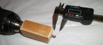
I start by using a 3/32-inch drill bit (roughly 2.5mm), and I cover the drill in a couple wraps of tape so that only the tip is exposed. This will center the bit in the threaded hole, and also give the existing threads a little protection. I had to apply new tape to the bit after each hole is drilled through.
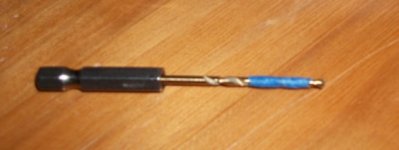
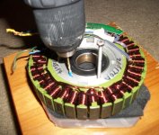
Clean out the aluminum shavings and the torn tape bits. I now took some scrap wood and used the 1/8-inch drill bit to make a drill-stop, which exposes only 8mm of the drills tip. Flip the stator over so the hall sensors are facing down, and drill the pilot holes out to 1/8-inch diameter (roughly 3.2mm)
View attachment 16
Now it's a simple matter to tap new threads into the holes. Start on the threaded side (hall sensors facing up). Make sure you bought an common 4mm X 0.70 threaded tap...I accidentally bought a 4mm X 0.75 (why do these exist?).
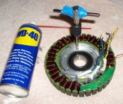
Tape over the bearing inside and outside. Tape is cheap. The bearings are cheap too, but my time for disassembly and replacing a damaged bearing is expensive, not to mention having to WAIT for the package to arrive in the mail..
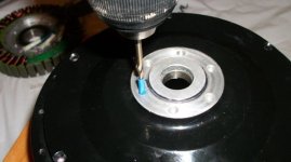
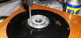
As long as I had the drill and taps out, I went ahead and drilled the six disc brake flange holes all the way through using the same method as above. The threads are 5mm X 0.80, so I used a tape-wrapped 1/8-inch bit (3.2mm) to drill through-holes from the threaded side. I flipped it over, and the aluminum was so thin at that spot, I hand-turned the drill bit with a screwdriver handle (my small bits have a hex-shaft). I used an 11/64-inch bit (0.172, 4.3mm), which is actually a perfect bit for this. Then, I started tapping the new threads from the threaded side.
If you look at the last few pics in this tutorial, you can see two additional holes in the perimeter of the sideplate on perimeter of the planet-gear side. They are threaded 4mm holes that can be used for jacking bolts to easily separate the motor-case/side-plates during any future dis-assembly. You would remove the six side-plate screws, put two of those screws in the threaded holes, and then turning them will lift the plate off. If you would find those to be useful, now is a good time to drill/tap them.
I have taken the yellow hall-wire, and slipped some heat-shrink (2mm or 3/32-inch) over it on the cable side, and I have stripped the insulation off the tip in preparation for soldering.
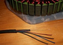
All five hall-wires soldered, and I have slid the heat shrink over them. Green, Red, Black, Blue, Yellow. Make note of the sharp edges in the aluminum stator-core right next to where the hall wires attach to the hall-sensor circuit board...bad design...dull the sharp edges and put extra insulation in that spot.
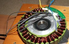
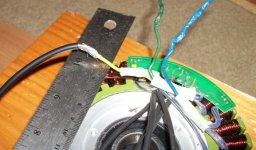
Now on to the stock three yellow/green/blue 14-Ga phase wires (which have very thin insulation). Here you can see the Yellow wire has had the tip insulation stripped, and it is mated with the 12-Ga Turnigy wire by the Amberwolf method. Not shown in this pic is the section of heat-shrink I slid on FIRST before mating the wire ends. 4mm heat-shrink would be tight on the 12-Ga part (with thick Hobby-King silicone insulation), 5mm heat-shrink might be a little loose after shrinking onto the 14-Ga section (It's smaller wire plus MUCH thinner insulation so it could fit through the hollow axle), and so I found that 3/16-inch heat-shrink (4.5mm) worked well for both.
If you had used the recommended method I highlighted above in red text, these stubs would be 7 inches instead of the 3 inches seen in this pic.
The steel ruler is there to protect the stator coils from solder drips, and accidentally dropping the hot soldering iron.
View attachment 9
Next step is to mate the stator to the magnet-ring "bowl". Make certain the large wavy spring washer is re-inserted onto the central magnet-ring sleeve and held into place with a dab of thick/sticky grease (only to keep it from falling off during re-assembly). My plan is to set the bowl on the ground, and then insert three 50mm-60mm long M4 screws into the stator-core so the ends protrude out the magnet bowl side.
I will set the stator over the magnet bowl, and then back-off the three bolts evenly to lower the stator onto the magnetic ring-bowl. The magnetic field should automatically center the two assemblies (it ended up having a tendency to pull to one side and then the other). I know they can be "plopped" together without jacking bolts, but the possibility exists that something can get dinged or stator-wire insulation scratched. Not to mention a finger-tip being smashed in spite of your best efforts.
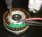
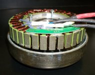
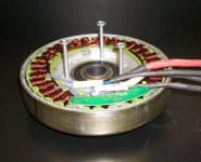
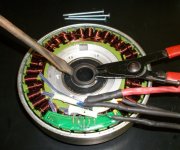
It appears I will be using 4mm hex-cap bolts that are 40mm long for maximum thread engagement (tightened by a 3mm hex-socket Allen wrench). With washers and lockwashers under their heads. The tips will protrude out just enough on the magnet-bowl side to be equal in protrusion to the coil-wire end-turns. I will re-use the lock washers that were originally used to secure the stator-collar, and green-machines sideplate is 6mm thick in the center. If you are using the stock MAC 4mm thick sideplate, I would advise using 35mm long bolts through the heat-bridge (http://www.mcmaster.com/#socket-head-cap-screws/=mho7ib).
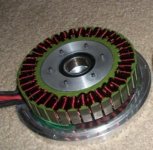
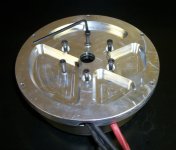
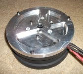
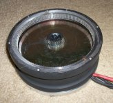
The pic-tutorial is continued here:
http://endless-sphere.com/forums/viewtopic.php?f=28&t=45245&p=735959#p735959
Also, even if you felt the 7mm deep threads are adequate, but you wanted full bolt penetration, you can drill out these holes from the other side to a diameter of 5mm and a depth of around 8mm (the aluminum is about 15mm thick at that spot). This way, you get full bolt penetration into the threads without having to worry about the exact length of the bolts, which often are sold in 5mm increments (30mm, 35mm, 40mm...). I will be using 35mm length bolts.
If you think you will be separating the stator from the magnet ring for any reason in the future, this "through hole" mod allows 50mm (or longer) M4 screws to be used as "jacking bolts" to slowly and easily lift or lower the stator into/out of the magnetic field.
I now realize I should have taped over the central bearing to protect it from the thousands of tiny shavings. I will do that every time in the future.
I start by using a 3/32-inch drill bit (roughly 2.5mm), and I cover the drill in a couple wraps of tape so that only the tip is exposed. This will center the bit in the threaded hole, and also give the existing threads a little protection. I had to apply new tape to the bit after each hole is drilled through.


Clean out the aluminum shavings and the torn tape bits. I now took some scrap wood and used the 1/8-inch drill bit to make a drill-stop, which exposes only 8mm of the drills tip. Flip the stator over so the hall sensors are facing down, and drill the pilot holes out to 1/8-inch diameter (roughly 3.2mm)

View attachment 16
Now it's a simple matter to tap new threads into the holes. Start on the threaded side (hall sensors facing up). Make sure you bought an common 4mm X 0.70 threaded tap...I accidentally bought a 4mm X 0.75 (why do these exist?).

Tape over the bearing inside and outside. Tape is cheap. The bearings are cheap too, but my time for disassembly and replacing a damaged bearing is expensive, not to mention having to WAIT for the package to arrive in the mail..
As long as I had the drill and taps out, I went ahead and drilled the six disc brake flange holes all the way through using the same method as above. The threads are 5mm X 0.80, so I used a tape-wrapped 1/8-inch bit (3.2mm) to drill through-holes from the threaded side. I flipped it over, and the aluminum was so thin at that spot, I hand-turned the drill bit with a screwdriver handle (my small bits have a hex-shaft). I used an 11/64-inch bit (0.172, 4.3mm), which is actually a perfect bit for this. Then, I started tapping the new threads from the threaded side.
If you look at the last few pics in this tutorial, you can see two additional holes in the perimeter of the sideplate on perimeter of the planet-gear side. They are threaded 4mm holes that can be used for jacking bolts to easily separate the motor-case/side-plates during any future dis-assembly. You would remove the six side-plate screws, put two of those screws in the threaded holes, and then turning them will lift the plate off. If you would find those to be useful, now is a good time to drill/tap them.


I have taken the yellow hall-wire, and slipped some heat-shrink (2mm or 3/32-inch) over it on the cable side, and I have stripped the insulation off the tip in preparation for soldering.

All five hall-wires soldered, and I have slid the heat shrink over them. Green, Red, Black, Blue, Yellow. Make note of the sharp edges in the aluminum stator-core right next to where the hall wires attach to the hall-sensor circuit board...bad design...dull the sharp edges and put extra insulation in that spot.

Now on to the stock three yellow/green/blue 14-Ga phase wires (which have very thin insulation). Here you can see the Yellow wire has had the tip insulation stripped, and it is mated with the 12-Ga Turnigy wire by the Amberwolf method. Not shown in this pic is the section of heat-shrink I slid on FIRST before mating the wire ends. 4mm heat-shrink would be tight on the 12-Ga part (with thick Hobby-King silicone insulation), 5mm heat-shrink might be a little loose after shrinking onto the 14-Ga section (It's smaller wire plus MUCH thinner insulation so it could fit through the hollow axle), and so I found that 3/16-inch heat-shrink (4.5mm) worked well for both.
If you had used the recommended method I highlighted above in red text, these stubs would be 7 inches instead of the 3 inches seen in this pic.
The steel ruler is there to protect the stator coils from solder drips, and accidentally dropping the hot soldering iron.

View attachment 9
Next step is to mate the stator to the magnet-ring "bowl". Make certain the large wavy spring washer is re-inserted onto the central magnet-ring sleeve and held into place with a dab of thick/sticky grease (only to keep it from falling off during re-assembly). My plan is to set the bowl on the ground, and then insert three 50mm-60mm long M4 screws into the stator-core so the ends protrude out the magnet bowl side.
I will set the stator over the magnet bowl, and then back-off the three bolts evenly to lower the stator onto the magnetic ring-bowl. The magnetic field should automatically center the two assemblies (it ended up having a tendency to pull to one side and then the other). I know they can be "plopped" together without jacking bolts, but the possibility exists that something can get dinged or stator-wire insulation scratched. Not to mention a finger-tip being smashed in spite of your best efforts.


It appears I will be using 4mm hex-cap bolts that are 40mm long for maximum thread engagement (tightened by a 3mm hex-socket Allen wrench). With washers and lockwashers under their heads. The tips will protrude out just enough on the magnet-bowl side to be equal in protrusion to the coil-wire end-turns. I will re-use the lock washers that were originally used to secure the stator-collar, and green-machines sideplate is 6mm thick in the center. If you are using the stock MAC 4mm thick sideplate, I would advise using 35mm long bolts through the heat-bridge (http://www.mcmaster.com/#socket-head-cap-screws/=mho7ib).


The pic-tutorial is continued here:
http://endless-sphere.com/forums/viewtopic.php?f=28&t=45245&p=735959#p735959
Similar threads
- Replies
- 12
- Views
- 2,180
- Replies
- 49
- Views
- 3,030
- Replies
- 4
- Views
- 196
- Replies
- 18
- Views
- 2,553
- Replies
- 83
- Views
- 14,373


