Normally I'd stick this in my CrazyBike2 thread as I figure it out, but this one is probably gonna take some outside help to figure out; I'm at the head scratching stage (I'm not much of an SMPS guy, really).
I will upload the pics as soon as I can get the bandwidth on the wifi I have access to, but I'm having a lot of trouble with that at the moment. For now, some descriptions will have to do (and I know it's not enough). Also, the pics I do have are pretty bad, as I can't recharge the android phone with the better camera on it yet; it's USB port needs repair and I've not had time for that either).
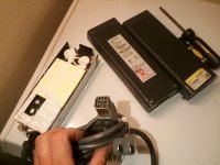
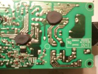
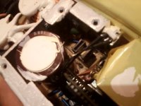
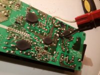
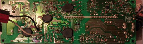
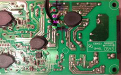
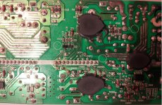
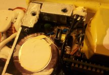
For now, it looks like this:

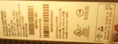
So...I found a 12V 16.5A power supply, apparently originally from an old XBOX, for a few dollars at Goodwill, and verified it works normally (green LED) under my lighting load on AC power, and it will power on to Standby mode (yellow LED) when hooked up to my ebike traction pack (at 57.4V at the time), with only one polarity on the AC input--the other polarity does nothing. More on that in a bit.
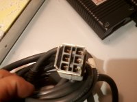
The standby mode is when it isn't plugged into anything, because it has a 5V pin and a Power Good pin on the output plug, whcih must be shorted together to turn it on (no 12V output until that happens). I did the shorting using a small-value resistor, in case it doesn't handle full 5V on that line very well, but it appears it would probably work fine even with a direct connection.
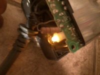
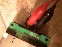
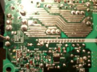
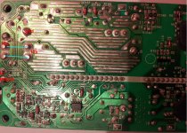
On the polarity thing: It appears there are a couple of places on the PCB where the AC side does cross over to the DC side, though I haven't traced the circuitry fully to see where they go. If I connect the DC input from the bike battery to the bridge rectifier's + and - "dc" outputs, then unexpectedly it does nothing at all. The reason for this is that those AC input crossconnections into the DC section seem to require the opposite voltage that they get if I hook up the DC input that way (but it would blow things up if I hooked up the DC the other way, of course).
When I hook the DC up to AC input in the polarity that works (for standby, at least), the voltages that appear at those crossovers are opposite of what they would be if I hook up the DC to the DC side of the bridge. If I hook DC up to AC input in the polarity that doesnt' work, then those voltages are the same as if I hook the DC to the DC side.
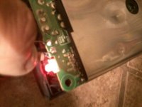
In either case, I can get it into standby either from DC applied to DC side, or one polartiy on the AC input side. But if I enable it, it shows Red LED for "fault" condition.
So...what I have to do is figure out what I need to change in the circuitry to put the correct voltages at those points, without shorting out anything else (probably will have to cut traces?), just so I can see if it will actually fire up and provide any 12V power on the output when running from the bike's traciton pack, as I want to use this as my lighting and accessory 12V power source, instead of the tiny little DC-DC I'm using now (whihc doesn't even put out a full 12V on the headlight cuz it needs more current than the thing can provide...much less the nearly 14V the headlight really ought to have).
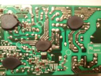
Note that normally it runs on 115VAC, whcih measures out as 170VDC at the bridge's DC outputs (and at the main cap hooked to them). I'm sure I couldn't get the full 16.5A (probably not evne half that) out of it on the voltage I will use, but even 6 or 7A would be enough to run the things I really need it for, and perhaps for short periods I could even use my headlight on "high beam", with both filaments running--I don't need that all teh time, but I do need it sometimes, and right now I can only do it if I carry a 12V battery with me for the purpose. The DC-DC I have is too small.
I've done some googling with what bandwidth I can get, and found a lot of places to tell me how to just do what I already did--enable it with the power-good pin to turn it into a "lab PSU", but nothing yet on how to power it from HV DC instead of AC.
I will upload the pics as soon as I can get the bandwidth on the wifi I have access to, but I'm having a lot of trouble with that at the moment.
For now, some descriptions will have to do (and I know it's not enough). Also, the pics I do have are pretty bad, as I can't recharge the android phone with the better camera on it yet; it's USB port needs repair and I've not had time for that either). For now, it looks like this:
So...I found a 12V 16.5A power supply, apparently originally from an old XBOX, for a few dollars at Goodwill, and verified it works normally (green LED) under my lighting load on AC power, and it will power on to Standby mode (yellow LED) when hooked up to my ebike traction pack (at 57.4V at the time), with only one polarity on the AC input--the other polarity does nothing. More on that in a bit.
The standby mode is when it isn't plugged into anything, because it has a 5V pin and a Power Good pin on the output plug, whcih must be shorted together to turn it on (no 12V output until that happens). I did the shorting using a small-value resistor, in case it doesn't handle full 5V on that line very well, but it appears it would probably work fine even with a direct connection.
On the polarity thing: It appears there are a couple of places on the PCB where the AC side does cross over to the DC side, though I haven't traced the circuitry fully to see where they go. If I connect the DC input from the bike battery to the bridge rectifier's + and - "dc" outputs, then unexpectedly it does nothing at all. The reason for this is that those AC input crossconnections into the DC section seem to require the opposite voltage that they get if I hook up the DC input that way (but it would blow things up if I hooked up the DC the other way, of course).
When I hook the DC up to AC input in the polarity that works (for standby, at least), the voltages that appear at those crossovers are opposite of what they would be if I hook up the DC to the DC side of the bridge. If I hook DC up to AC input in the polarity that doesnt' work, then those voltages are the same as if I hook the DC to the DC side.
In either case, I can get it into standby either from DC applied to DC side, or one polartiy on the AC input side. But if I enable it, it shows Red LED for "fault" condition.
So...what I have to do is figure out what I need to change in the circuitry to put the correct voltages at those points, without shorting out anything else (probably will have to cut traces?), just so I can see if it will actually fire up and provide any 12V power on the output when running from the bike's traciton pack, as I want to use this as my lighting and accessory 12V power source, instead of the tiny little DC-DC I'm using now (whihc doesn't even put out a full 12V on the headlight cuz it needs more current than the thing can provide...much less the nearly 14V the headlight really ought to have).
Note that normally it runs on 115VAC, whcih measures out as 170VDC at the bridge's DC outputs (and at the main cap hooked to them). I'm sure I couldn't get the full 16.5A (probably not evne half that) out of it on the voltage I will use, but even 6 or 7A would be enough to run the things I really need it for, and perhaps for short periods I could even use my headlight on "high beam", with both filaments running--I don't need that all teh time, but I do need it sometimes, and right now I can only do it if I carry a 12V battery with me for the purpose. The DC-DC I have is too small.
I've done some googling with what bandwidth I can get, and found a lot of places to tell me how to just do what I already did--enable it with the power-good pin to turn it into a "lab PSU", but nothing yet on how to power it from HV DC instead of AC.