Cover Drilling Tips

icecube57

10 MW
Joined
Apr 25, 2008
Messages
3,073
Location
Austell GA
For the HS and HT Crystalyte Motors.

Its 72mm between each cover bolt hole. So its 36mm directly in between the two. If you mark that point inbetween the two holes thats your center point obviously. The point should line up directly across a hole on the other side of the cover. You should be able to take a sharpie and link the points together. Now that you have your lovely star pattern you can go to the next step. Now the channel thats used to give the windings extra space is 20mm wide so 10mm should be the center point of that. Your lines should make a perfect cross hair to serve as your drill point to make your holes.
 
Why worry about a pretty pattern only to put holes of the wrong size in the wrong location? The focus should be on optimizing flow along with directing the flow in a way that maximizes turbulence at the stator iron and end windings. Maximizing flow results in the air flow to be able to carry more heat out of the motor by increasing the delta T, and increasing turbulence where the heat is generated increases the convective heat transfer coefficient.
 
Your point is very true and well taken Umm who has a wind or water tunnel to test and prove these theories to where its not snake oil.
 
Email mythbusters. 8) They'll bust it or confirm it.

I take a simple approach. If you can't see how toasty brown the windings are getting thorugh at least some of the holes, you did it wrong. To my mind, that's the hot place you want the air to leave, or enter easiest. So at least one side has to have big holes you can see winding through.

Here's a tip, remove the cover before you drill. :wink:

I do agree, don't drill too close to the bolts. Give the cover it's full strength near the bolt holes.
 
icecube57 said:
Your point is very true and well taken Umm who has a wind or water tunnel to test and prove these theories to where its not snake oil.

"Snake oil"...rotflmao. If I didn't find it so funny, I'd find it offensive. Continuing to promote SteveO's original experiment from 3 years ago as "the" way to ventilate a hubmotor, while ignoring research, experimentation, and real world proof of ways to improve upon it is like explaining how to install a stone wheel on a bike.
 
Well....Back to a tip: To finish off a hole to the exact diameter that you want with smooth edges, a Unibit comes in very handy. You can mark the unibit with a Sharpie at the level 1 step higher than the size you want to finish at. Turn the cover around and give it a little touch up by beveling the backwide of the hole.
 
dogman said:
I take a simple approach. If you can't see how toasty brown the windings are getting thorugh at least some of the holes, you did it wrong. To my mind, that's the hot place you want the air to leave, or enter easiest. So at least one side has to have big holes you can see winding through.

Guess how many of my ventilated motors have toasty brown windings....None. Why do you think that is, because my motors are magic, or because they're well ventilated? It's certainly not from running them at low power. :D

While the windings are visible looking at the motors in line with the bike, looking directly from the side they aren't. If the windings are in plain view from the side, then much of whatever flow you get will escape through the holes before having a chance to flow over those end windings and help cool them.
 
Gregor said:
Well....Back to a tip: To finish off a hole to the exact diameter that you want with smooth edges, a Unibit comes in very handy. You can mark the unibit with a Sharpie at the level 1 step higher than the size you want to finish at. Turn the cover around and give it a little touch up by beveling the backwide of the hole.

You want half of the edge sharp and half rounded. Whether it's the leading or trailing edge that's sharp and angled depends on whether it's an exhaust hole at the extreme perimeter or an intake hole closer toward the axle.
 
I know there my downfalls are.. to small of a motor thats easily saturated at the power levels Im running. The wrong wind for my terrain. But venting does help wheter its active or not. It does create a threshold where it does aid in the temps not climbing above a certain point and its defintely better than non vented. If there was scooops or something i could snap into my holes to redirect air directly to the stator i would. Im not that talented and everyone would say its hogwash.
 
icecube57 said:
If there was scooops or something i could snap into my holes to redirect air directly to the stator i would. Im not that talented and everyone would say its hogwash.

John in CR's hubbies are MUCH larger units designed for mopeds. Small wonder that with even the slightest of modification ..they run cooler when wedged in a bicycle frame. Good stuff, but that is like comparing apples to bacon (mmm, bacon).

Snap in scooops?! That is a great idea for cooling hot-rodded eBike hubmotors, Ice!

Hogwash, TurdPolish, who cares what gets applied -- as long as the magic smoke stays in, right?

This concept merits investigation/design/development.
 
Stevil_Knevil said:
icecube57 said:
If there was scooops or something i could snap into my holes to redirect air directly to the stator i would. Im not that talented and everyone would say its hogwash.

Snap in scooops?! That is a great idea for cooling hot-rodded eBike hubmotors, Ice!


This concept merits investigation/design/development.

:idea: Seems like a nice project for someone with a 3D printer ! :idea:
Also, what about a small blower motor pressurizing a "manifold box" with an outlet slot on the same PCD as the inlet holes on the hub.. ?
.. ? probably not enough room, and also likely a bit of overkill !. :?
 
This i a pefect thing if projection molding could be done and holes were in a specifc range where on size fits most in a specifc size range depending on hole size but there is several things we gotta look at... motor and caliper clear and stuff so what i a good idea for some isnt a good idea for all. Also we have all these builds on water cooling. I know air is a poor transferer of heat but what if the hub was pressurized in general in general som. Im trying to figure out if small preforated copper tubing the size of lie pencil led can be tucked in to the outer lip of the windings and co2 from a paint ball tank could somehow be regulated in to do short quick cooling. Seems like even teflon tubing could do the job. But CO2 does come out under pressure but the holes have to be small enough to keep the pressure up to where it forceful and not have so many holes that it never makes it to the end and also depending on how the bottle is tilted and does come out in a super cooled liquid state lol just thoughts.... Now all of this is hog wash but i wish i could make it happen.
 
Hey, just trying to get the idea across, don't drill all your holes near the axle. If cover design allows, definitely ventilate so wind flows across the windings. On many bike motors side holes are as good as you get.

That good enough? I didn't call your method snake oil or knock it in any way.

You tend to use motors that can handle the current you are using. Most of us idiots are still under the delusion that a 9c can handle 3000w, and a Clyte HS 5000. So we do toast windings nice and brown, if not black. It's nice to peek in and see how black so far.
 
Stevil_Knevil said:
John in CR's hubbies are MUCH larger units designed for mopeds. Small wonder that with even the slightest of modification ..they run cooler when wedged in a bicycle frame. Good stuff, but that is like comparing apples to bacon (mmm, bacon).

Only one motor is larger, and that's the one I was running at 30kw input without heat issues. The 9C worked fine, but is on a shelf because both irfb4115 controllers blew, and I've been unwilling to pursue it. It's simply not capable of the power I demand anyway, so will eventually go on a kids gokart or something, since it's been modded for mid-drive only.

My other ventilated motors have a 40mm thick stator and are of a design copied and used in the 9C, Xlyte H series, Cromotor, etc. I say copied since the factory I got them from 4 years ago holds the Chinese patent. For all I know that factory makes the stators and sells them to these smaller motor winding and assembly operations, since stators, rotor rings, covers, etc can be purchased in China as parts. The point is that they're theoretically about 1/3 more motor than a 9C, 14% more motor than an Xlyte H series, and 20% less motor than a Cromotor. Just because it has a thicker axle with wider spaced flats, and one cover has a drum brake is all irrelevant to performance or ventilation.

I'd get into how their 2 turn windings make them a more powerful motor with our practical 100V limit, but that's beyond the scope of icecube's topic, and is only relevant to cooling in that I have to reject more heat simply because I run higher power. My vented motors aren't more efficient. In fact, they're less efficient in real world use because they're not as efficient during acceleration, so they have to reject even more heat.

I run them in 20" wheels resulting in 15% higher rpm than a 26" wheel, and that aids in cooling, but the wheel size definitely doesn't account for all of the difference, and anyone can run a 20" wheel.

It's definitely an apples to apples comparison.

John
 
Something that would be killer, is to burn something smokey, and set it near the inlet holes on your hub with the wheel off the ground spinning. If the smoke sucks in the holes and blows out the other side, we can put that whole discussion to rest.

Seems like a pretty easy video to make. If you had a little smoke bomb firework it would be even easier.
 
Supid idea but how come one could take lets a 40-mm fan and a correctly sized pvc pipe and reduce it down to the size of the holes of the motor... line it up and duct it in. or would the forward wind resistance overcome the thrust generated. or even what about a fan motor like they use on fords that have a sprag clutch that grabs at a certain rpm and spins closely over the cover and let go and spin down below a certain speed seems like that could be internal if not external. Anyone study golden motors design yet.
 
I'm with dogman on this topic. Seems the holes should be next to the part that generates the most heat, as a vent. That way heat escapes easier, and is effective when you notice you're melting the motor and stop. Perhaps there is not as much air flow or turbulence as the I/E design, but than again do I really want an "intake" on my motor? Rocks, dirt, water getting sucked in easier?

I think there is merit to intake/exhaust airflow design, and don't discredit it, but it would work way better with louvers. The trick would be to basically make the side covers the fan. They are already there, and already spinning, so why not? This design also becomes less effective if stopped.

My 2 cents
 
icecube57 said:
Supid idea but how come one could take lets a 40-mm fan and a correctly sized pvc pipe and reduce it down to the size of the holes of the motor... line it up and duct it in. or would the forward wind resistance overcome the thrust generated.
A regular case-fan type won't generate enough air movement to help, especially under already-turbulent airflow conditions, and even under ideal conditions can't really compress air down into a funnel very well.

A squirrel-cage type probably will, and is easier to funnel down--it is a common application for them, and is why they are used as blower motors in air conditioning systems.

Lowracer does ducting of air into a set of holes on his motor; I'm not sure how well it works but if you can reach him he might have more info than what is in his threads (as his videos are gone, which contained most of the information).
 
liveforphysics said:
Something that would be killer, is to burn something smokey, and set it near the inlet holes on your hub with the wheel off the ground spinning. If the smoke sucks in the holes and blows out the other side, we can put that whole discussion to rest.

Seems like a pretty easy video to make. If you had a little smoke bomb firework it would be even easier.

I did that once but couldn't generate enough smoke for it to be visible coming out. The only thing it clearly demonstrated to me was that the motor started sucking smoke in below 10mph. A stationary spinning wheel isn't the same as a wheel rolling down the road anyway, so it wouldn't be proof.

Proof is powering up a mountain using 160wh/mile and having a cool motor at the top, and that's been done and shared on video, yet some still question the results. That takes a lot of nerve when their bikes can't do that kind of climb even with 100lb less weight on their bike and 10mph lower speed, much less without a hot motor. They have a hard enough time fighting hot motors on mostly flat rides.
 
A lot of these type of threads focus on dynamic cooling--the type you need going up an 8% grade for 5 mins or more, but many of us only use 1500 to 2500 watts for 30 to 60 seconds at most. If we had the exeption to the rule type hill, then I would ride up it for 5 mins, stop and feel my controller and hub, smell for that distinct "burming windings smell", maybe smell the roses, and write myself a note that I need to buy a temperature gauge so that I don't have to stop so often!
 
liveforphysics said:
Something that would be killer, is to burn something smokey, and set it near the inlet holes on your hub with the wheel off the ground spinning. If the smoke sucks in the holes and blows out the other side, we can put that whole discussion to rest.

Seems like a pretty easy video to make. If you had a little smoke bomb firework it would be even easier.

John in CR said:
I did that once but couldn't generate enough smoke for it to be visible coming out. The only thing it clearly demonstrated to me was that the motor started sucking smoke in below 10mph.

Which motor, John? Did you try it on both sides, or just the side you expected it to be drawn into?

Not even challenging your (generally awesome) performance, just the process..
 
Here are some ineffective pretty holes ive done.
 

Attachments

  • STA71190 (Small).JPG
    STA71190 (Small).JPG
    34.6 KB · Views: 1,096
Stevil_Knevil said:
Which motor, John? Did you try it on both sides, or just the side you expected it to be drawn into?

It was the motor on my son's Clown Bike, call it an H40. It has one sided intake and exhaust out of both sides. If you mean did I try to make it intake at the ring of exhaust holes, no of course not, but I did put it near there to see if it could demonstrate the outflow of air that I could feel coming out, but it just made the smoke disappear. I did that 2 years ago, and did think about using a smoke bomb since fireworks are available down here. I nixed that after remembering how they stained the concrete when I was a kid, and I didn't want whatever those chemicals are on the inside of my motor in case it reacted with the plastic on the wiring or varnish on the windings.

Hubmonster isn't on a bike right now, so I could very easily put it in the vise, burn something to create smoke, and use my camera that can take videos (crappy but good enough capture this), figure out how to post a video, and show the motor sucking smoke in the intake. Since it has exhaust only out of the other side it might even capture that the smoke is coming out of the motor on the exhaust side.

I actually want to test intake at the top rpms anyway, because spinning the motor up on the bike, I stuck my hand carefully near the exhaust that's recessed in the rim on that motor to feel the flow. At moderate rpms I could clearly feel air blowing out, but it seemed to diminish as rpm neared no load speed. I couldn't tell if it was reduced flow or that the cover bolt heads or the raised ridges on the cover were creating enough turbulence that I just couldn't feel it anymore. I'd like to find out if it really was reduced flow, because I need to fix that to run at higher voltage. If true then I suspect it's from not enough intake area to support the higher flow of the higher rpm and as a fan it gets starved of air and stops blowing much air at all. If you've ever restricted the intake of a server blower to a point where the sound changes pitch and output flow drops drastically at the same time, then you understand my concern. The motor does get warmer on the highway, but never hot, so I haven't worried about it. The solution is more intake holes or enlarging those I already have, which means opening the motor, something I'm loathe to do if it means pulling the wire side cover, the intake side, because it would require redoing the motor harness. :idea: I can easily pull the other side and magnet ring, so maybe I can get comfortable that I can blow out any AL shavings and just drill it while on the stator.

If it would really put the matter to rest once and for all, I'd go for it, but it won't, because of the valid point that the exterior influences are different spinning stationary vs rolling down the road. The simple fact that air has mass is already proof enough for me. For those who don't get that part, then powering a 360lb load 4 miles up a steep mountain road, riding hard enough to get 4% regen braking into the corners going uphill, while consuming 160wh/mile, is a slam dunk as far a proof goes. Hell, Itchynackers ran hot up pikes peak with an oil cooled motor using far lower power, pedaling his ass off, in much colder ambient temperatures. Sure his covers have less surface area, but not 5 times less, and mine don't transfer any heat to speak of anyway, since they stay near ambient temp and heat transfer isn't possible without a temperature differential.

The heat doesn't go thru the covers. It's not stored in stator because hot air would rise out of it when we stopped at the top. Hubmonster is no more efficient than typical ebike hubbies, so it's not magic. If the ventilation approach doesn't work exactly in the common sense manner that I've explained a number of times, where does all that heat go? It can only go right out the exhaust vents with the centrifugal flow of air.

John
 
icecube57 said:
Here are some ineffective pretty holes ive done.

At least they look to be pretty close to the perimeter. It's just that the size would allow a significant portion of the flow to escape too soon, but that doesn't really matter, since unless there are intake holes that I can't see in the pics there won't be any meaningful flow at all. Its is better than sealed? Sure, since some hot air probably escapes, and the holes probably create some turbulence there.

Why post the pics though? Do you want someone to copy it, like so many have done for nearly 2 years? What research did you put into the design? Please explain how fresh cool air gets into the motor and hot air escapes.
 
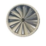
Here is my idea in graphic format, used some internet images and photoshop to get the idea. Both sides would have the fins pointed the same way in order to have the entire side be an intake, and the other side be an exhaust. Probably have the intake on the disk brake side in order to not expel heat onto the rotor.

If you really wanted to get nuts, this could be designed with a collective pitch rotor system, so the fan blades could really move some air at 15* pitch, or be completely closed for wet or dirt riding that does not need cooling. Wishful thinking there, but I do believe some static rotors like this picture would work better than any current solution.
 

Attachments

  • hubcover.jpg
    hubcover.jpg
    7 KB · Views: 1,068
Back
Top