CRF #2 - 250R - LGX P41A 20s1p - EM200

bananu7

10 kW
Joined
Sep 27, 2024
Messages
543
Location
Poland
Sooo.... I might have bought another bike.
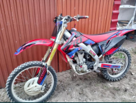
crf_old.png

It's a yet another 2005 CRF 250R, virtually the same as CRF #1. This has been going for a while behind the scenes, but I wanted to wait for a bit before I posted so that I at least had the bike on hand.

I should probably say why I'm even getting into this while #1 still isn't finished, with at least a couple dozen hours of work left still. Thing is, even in the unfinished state, it has given both me and other people so many smiles and pleasant moments, I just wanted to have a second one to share with people, do dual test-rides together, and just have double the fun. I also had some leftover parts, but most importantly, I already put so much effort into learning all this, it just didn't feel right to build only one bike. So when this one showed up, I pulled the trigger and ordered it shipped, without the engine.

This one isn't a project someone started, it sits as it was, just minus the engine and exhaust. Considering I did virtually everything on #1 myself anyway, I'm not too concerned. So let's look at the planned specs.

* Honda CRF250R motocross frame from 2005
* QS138v3 - exactly same one as in #1, new version, no surprises
* Votol EM200S - I got it because it was shipped from Poland and was really affordable even compared to the 260S. It can run at up to 250bA which I think should be just fine, especially given it's the "large radiator" version. The only thing that's concerning is if I'll manage to fit the radiator on the bike, as it is quite bigger than the 260. I thought about getting a 96V Fardriver as well, but the cost just didn't seem to justify it.
* LGX P41A cells. I'm going with a 20s1p with this one, with 41Ah cells. They have 204A continuous and 380A peak discharge rating, so hopefully they'll be up to the task. I'll put them in a support frame and enclose in fiberglass again. The cells weigh 660g each, so hopefully we'll shed some weight from #1 without sacricificing performance. I got them brand new, likely rejects, for a really absurdly low price of around 11.50 eur / cell. That's 230 eur for a 72V41Ah battery, which is impossible to match with cylindrical cells, and should save me from welding - I'll just clamp the electrodes together.
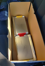
baterie.png

Another upside of using them will be much smaller battery size.

I'll likely start with 15-54 gearing with this bike to make it faster with more range, but less uphill pull. That means I can reuse the steel 428 54T I already own, for a really durable drivetrain; I'll just need a new chain. Other than that, I plan to keep the bike in original plastics and look.
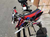
honda_paleta.png

The long-term plan for this bike is to get it to rideable state as quickly as possible, enjoy during the summer and sell right after, for a small profit that could fund more projects. As such, I likely won't be going into as much detail work as with mine, and just get it to work well enough for an average dirtbike rider/newbie. It will definitely get a better rear tyre (thankfully the seller has included one that's still usable). I will need to do a basic front suspension service, as they lost most of their oil during upside-down transit, and give it all a good clean and grease job.

I've ordered a Surron throttle for it as well, so it will be interesting to compare it to my cable throttle.

As always, questions, comments and words of encouragement are welcome, as well as visits if you want to ride it once it's complete ;)
 
IMG_20250524_122307.jpg

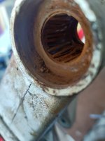
I stripped the #2 down to the frame today, for cleaning and inspection. Swingarm bearings are rusty and likely shot beyond repair. I do have another swingarm with the broken adjuster, so I could either move the bearings or repair the adjuster.

I also finally got the front wheel free. When the seller shipped it to me, he pulled the fork together with the front wheel out. Turns out one of the axle pinch bolts was welded to the aluminum block despite nickel coating.

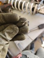
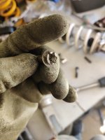
I took a trip today to get a 600Nm air impact wrench, but the socket just rotated on the bolt. Tried cutting it and using a flat head but the one of the flat bits chipped, and the other twisted:

IMG_20250524_111112.jpg

In the end I used a regular hammer with a good screwdriver and tapped the bolt loose. It's a small miracle I didn't damage anything else in the process. PSA: please use copper grease and a torque wrench in aluminium treads.

IMG_20250524_111100.jpg
 
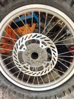
I had a bit of time today so I decided to take a look at the rear tyre situation. Long story short, both tyres landed in the trash and I'll get a Shinko 505 or 525 for it (and maybe a fresh front one while I'm at it). The good news is that the rim seems straight and with no dents, with just a couple of rusty nipples. Rear disc is shot which explain horribly crooked rear pads. Oh, and the wheel used to have bearings at some point, I'm sure.

All in all we're getting a couple new items to order, and given the overall bike condition I think I'll check other bearings and get everything in one go. Thankfully those things aren't too expensive when ordered individually and not in dedicated kits.
i don't seem to recall having that bad of a bike when I bought some bike previously, but with the Suzuki (bought with a shot engine) you can really tell it finished it's ICE life with proper hack mechanics. At the same time spending more than bare minimum for an electric conversion doesn't make much sense financially so I guess we are destined to have to fix these sort of things 😅 At least now you have loads of spares and you are proficient in 2008 CRF lol.
 
I guess we are destined to have to fix these sort of things
The first one I bought was supposed to be in well-maintained state, with everything replaced. That was true, the issue was it was all replaced incorrectly. I'd much rather do the regular maintenance job myself than fix a half-assed garage repair someone else attempted.

Honestly #2 isn't in that bad of a condition, it's just regular wear. Nothing seems outright damaged (I'm especially pleased with the wheels so far), just needs fresh consumables, which is about a perfect state for a conversion/restoration project (because that also means I could grab it for a fair price).

I have a budget in mind for this project because it was supposed to go on sale, and that includes a buffer for things like that, so all good.
you are proficient in 2008 CRF lol.
At some point I realized that #1 is actually a bike from 2005 as well :D. The seller didn't really know or care I suppose, I figured it out once the parts I ordered didn't really fit. They didn't change much over the years though.
 
I did some research and related shipping. I always like to post such stuff into logs for posterity.

The 2005 CRF has
* 25x42x9 6905 rear wheel bearings (x3)
* 20x37x9 6904 front wheel bearings (x2)
* 32x43x7 rear wheel seals (x2)
* 26x37x7 front wheel seals (x2)

To replace them, you need a 47mm OD special 6-sided tool.

I took a chance and ordered bearings from MGK, which I think is a Polish company. They had very affordable SS 2RS options (double seal, stainless) which should work great as wheel bearings.

For the rear wheel, I decided on Dunlop D952 in a 110/90-19 size I thought about going even smaller, with 100/90, but the larger one was slightly cheaper and I figured for the trail riding with a 19" i might want a bit more rubber at lower pressure. In fact, browsing through the tyre options is slowly convincing me that I might actually want to go with a 18" if I ever get to replacing wheels in the #1 CRF.

With the new rear brake disc and the new steel sprocket I have, I think the rear wheel is (will be, once I get and mount all of this) pretty much there, but I'm also considering replacing the spacers. This is annoying because I already ordered a set that didn't fit, despite all websites listing them as fitting "2004-2009" models or somesuch. Worst case scenario I'll just machine them myself. Hmm, now that I wrote it, I remembered that I might need a new rim band...

What else is there? Sprocket bolts looked good, disc bolts looked good, tube looked good. I think that's pretty much it.
 
Fun development! I am now pretty sure that my rear wheel (or at least the hub) is from mid-2000s Kawasaki KX250. They share the same axle diameter (25mm) with the CRF, but use different diameter seals (42 instead of 43mm), and the sprocket and disc are totally different sizing. I spent a good part of yesterday's evening cleaning everything and putting the new tyre on, just to realize the sprockets i have don't fit - and neither would the brake disc or the seals that I'm getting today.

So now I have a bit of a dillema - either build this wheel back (with a fitting disc, sprocket and seals - at least the bearings are the same) and hopefully it will all fit, or get a used CRF wheel and simply swap it in. I think this wheel looks fine, but I'm a bit concerned about the sizing/spacing. If the rear disk is offset by a small amount, the rear brake carrier has no chance of fitting it properly. I saw it had extremely crooked pads but I attributed that to disc wear, hopefully it wasn't actually forced in or anything. I can machine new spacers if need be but that might put the wheel off-center...
 
You're going into small series production;)
Too bad it's entirely dependent on the supply of used frames. Good that Honda made so many of them :D

I'm now pretty sure I do in fact own a KX250 rear hub. I found a disc for it, but for the sprockets I was in a pickle again - as I am determined to stay on the 428 chain. MJ corse actually has a 56T for KMX200 / KDX 125, but that's another pricy item. Instead, as I wanted to make the bike a bit faster anyway, I opted to go with JTR459.52 steel rear, which with 14T front will give me 8.73:1. I will definitely need a new engine mount, but I have to make one anyway.

As far as the wheel alignment, I was thinking about it, and correct me if I'm wrong, but with a floating brake, the exact location of the disc shouldn't matter, no? As long as the brake has enough slider/caliper space, it should self-center, so as long as the disc is roughly in there, it should all work fine.
 
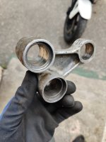
I disassembled all the swingarm and rocker bearings today. Everything is complete trash, rusted out as I was expecting at this point. I'll grab a kit from Aliexpress, as that comes out to less than half the price, so mechanically I likely won't put it together until next week. Unfortunately the swingarm is also eaten by the chain, which I specifically asked the seller about and he claimed that wasn't the case. I think I'll just use some epoxy metal putty and fill that in rather than try to weld like I did with my 990 swingarm.

The frame also has a couple bends, I suppose it didn't have an easy life. Everything is still reasonably straight and I don't think it's going to impact the durability all that much, but that's yet another item to check when buying older/used bikes.

At least the steering head bearings are fine - show slight signs of wear visually, but not enough to warrant replacing yet.
 
I was doing mostly text uploads recently, so here's some pics to balance it off.

Here's the before:
IMG_20250531_145613.jpg

And after:
IMG_20250601_175357.jpg
Getting the last pair of bearing races off was an adventure. I did add a couple scratches to the link, but hopefully nothing impacting the functionality. New bearings are on the way to me, and hopefully I'll get it working like new.
 
Last edited:
We're back in the back wheel game.
IMG_20250605_145614.jpg
IMG_20250605_145452.jpg

The Kawasaki parts are, unsurprisingly, a perfect fit. Bearings are in the freezer, and I'll check the wheel alignment when I get them in. Reminds me, I need to order another set of seals, as Kawasaki uses a smaller diameter.

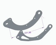
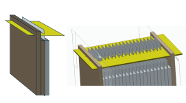
On the battery front, I'm still pondering on making the cell clamps. This is the shape i had in mind:

1749129881136.png

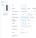
You can imagine the matching part (with a slightly steeper angle) that would clamp the electrode in between, putting a direct pressure point in a line shape between the electrodes. $158.40 for 20 pieces (so about $300 for a matched set) seems a bit steep though. I could buy a small milling machine for that price and just make them myself...

Another alternative would be to simply 3D-print those blocks. They carry no current, they're only supposed to press the electrodes together. If I made them stiff enough, I see no reason why it wouldn't work, especially printed in e.g. HTPLA to make sure they won't get soft if the battery heats up during use. Heat is a concern, though, as the electrodes carry the heat away from the cells. Aluminium blocks would be safe up to high temps, but also they would actively soak the heat out of the battery. PLA prints, OTOH, are excellent insulators, mostly due to the volume of air they contain inside but also to poor thermal conductivity.

What are your thoughts on it?
 
Last edited:
After mounting the disc, I did some fitting:

IMG_20250605_190107.jpg
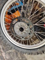
While a sliding caliper brake should be able to adjust quite considerably to a disk that's off-center, it needs clearance to do so. According to my measurements, the Kawasaki wheel puts the disc 3mm inwards compared to Honda, and just barely rubs on the caliper carrier. The caliper in question looks... questionable.


IMG_20250605_190552.jpg

You're seeing it right, the entire inner side seems crooked and chewed. It could have been caused by that wicked rotor being forcibly mounted in there. Either way, it's seized, pins are shot, complete trash. I'm starting to think the frame really wasn't a good deal at all :(

The good news is that AliExpress has everything now, including rear brakes with carriers fitting the bike perfectly. I think that if I dremel out that 3mm of extra material (actually less, as I just need it to barely clear, so it's more like 1mm) the stock caliper should sit on the rotor just fine. Fingers crossed, but that will have to wait about two weeks until it gets here, together with the bearings.

Oh, right, speaking of bearings. I put the new wheel ones in the freezer, but the right-hand side popped in surprisingly easy. Imagine my face when I was able to push it out by hand... I think the hub might have been damaged/enlarged slightly to the point when there's just enough play for it to wiggle. Thankfully, Kawasaki puts a circlip on that side, which after installing held the bearing firmly in place. I'm sure that with a new bearing it will work just fine, but it's something to watch for if it ever seized up and started rotating in the hub.

The front wheel bearings are acceptable, I'll just put new seals in. I actually had them, but misplaced them somewhere in the overcrowded mess that's my garage these days. I had to order new rear ones anyway (1mm smaller for Kawasaki), so no biggie.

So, while I'm waiting for parts, I can pause the mechanicals for a bit (as I imagine this might be boring for a lot of people wanting to read about electric vehicles) and focus on the battery. I've decided to go with the 3D printed clamps. The rationale is as follows - it's a process I know well, can do in house, will cost nothing, can be redone if necessary and, most importantly, i can simply set the battery operating temperature to under 50C inside, which is already too much. I'll just cut the power at that point and call it a day. If it ever gets that hot, that means it's undersized anyway, and at 150A continuous I'm planning on pulling, the cells should barely heat up.

I'll get to printing, but I have to figure out the geometry. Basically I was thinking I could either make the clamps be a mirror of each other, meaning the will contract to two flat surfaces, or make the top "V" sharper, so that it focuses the pressure in one point. My thinking is that if the electrode is flat, clamping them in one spot that's as thick as the electrode itself (so say 0.5mm in width) would form a continuous current path not worse than the metal itself, and maximizing pressure means minimizing resistance. On the other hand, spreading the pressure over a larger area means more opportunity for the degraded contact to restore the resistance back to uninterrupted metal, if there's any contamination, for example. So I'm thinking I might go for something like 1-1.5mm of clamping edge, as a balance between the two.

I've also realized that I'll need to attach the busbars at the end electrodes. I suppose in this case going with two copper bars is my best option. I'll post the CAD designs for the battery once I'm done with them, hopefully soon. I need to order at the very least the FR4 carrier boards, but I still have nothing for the sides and compression.

P.S. One more thing about the rear brake - another option would be to machine a 2-3mm spacer that would go between the swingarm and the carrier, and another spacer to replace the stock one that's 2-3mm shorter. I'm concerned about the brake carrier stability then, though, as by default it seems to touch the swingarm at the wider area. There's also the sliding part that goes into the channel in the swingarm, and that can't get loose or else bad things will happen.
 
Last edited:
I did some design.

1749408346722.png

The new one puts the motor 10mm higher (from the ground plane). It's also about 30% lighter than the previous one - I even did a weight reduction cutout!

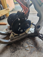
Turns out a QS138 mount will indeed fit on my printer in one piece.

1749408391257.png

And 3h later, we have it in the frame:

1749408478874.png

This tells me a couple things. First, I triple checked, and in the 250R frame it's just plain not going to happen with the plate on the outside. I'm missing like 4mm to the chainline even in perfect scenario. At this point I'd be limited by the swingarm. I know that the lithiumkings mounts have a bent plate for that reason, but I see no point doing that. The internal mounting plate in #1 works just fine, so I'll just copy that.

Second, it's going to be impossible to check the vertical position (and backwards) without the swingarm, wheel and chain on. So even though it's very likely this is a final design, I have to wait for swingarm bearings to get here to do a mock fitting. I might print a second side for stability, although it's really not required for this kind of check.

1749408692771.png

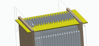
I'm slowly chipping at the battery as well. As you can see, I've run into an issue where the side plates go where the final busbars would attach. I need to figure something out for those ends.
 
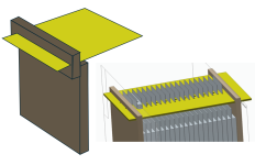
Could you make a staggered sub-plate at the top? Preferably welded or maybe riveted/bolted? That depends on the materials you're using though. Please pardon the crudeness of my sketch...


1749419273300.png
 
Could you make a staggered sub-plate at the top? Preferably welded or maybe riveted/bolted? That depends on the materials you're using though. Please pardon the crudeness of my sketch...

If the plates are primarily there for compression, then that will change the spread of forces across the plate and probably not produce even compression across the cell surfaces.
 
What if the smaller plate only at the top, actually extended to the base of the other inner shorter plate? That would maintain the even compression you rightfully mention @amberwolf. These ideas might be errant if the case has dimensional constraints. *shrug*
 
What if the smaller plate only at the top, actually extended to the base of the other inner shorter plate?
I don't understand what you mean.

If you mean having the small plates both part of a single U-shaped top plate, that won't work for compression because it would prevent them from being pushed toward each other by the tensioning hardware. It also won't work because it still doesn't provide a single stiff surface to cover and compress all of the largest cell surface.

If you mean something else, you'll have to either more precisely explain or show an image. ;)
 
Yeah, something like that could work. I'm also thinking about making a cutout in the middle and simply rely on clamping forces in the corners. I'll mock it up later today. I have no idea what the plates are going to be made of yet, so this is still a very early sketch. If they were e.g. 3D-printed, I'd get a lot of freedom. I'm thinking fiberglass could also work really well here. Something that's stiff enough that when clamped with 4 threaded rods in the corners will compress the cells enough.

I have a reasonable amount of space, as this battery is much smaller than the #1 anyway, but if it grows too much in all directions, it can become tricky to fit again.
 
I recommend checking out the end-plates for existing compressed packs to see what they did, for design proportions, reinforcement ribs, shape, etc. There's a number of such packs posted around ES, some of which were images from greentecauto, batteryhookup, jag35, batteryclearinghouse, and various other battery makers and sellers.

As long as whatever you use or make can't be twisted or bent under however much force it takes to compress the stack over it's full surface area, the plates will transfer all the corner-bolt force to the cell faces. If the ends don't have to be completely flat, you can have a raised section in the middle with ribs spreading out to the corners to better distribute the forces, like gussets.


If necessary you can use straps instead of bolts, there are a few solutions that do that. Some of the straps are essentialy big worm-gear clamps (like radiator hose clamps), some are more like the tensioning straps to secure palletized items (which come in manually-adjustable versions, and machine-installed-non-adjustable versions, and variations of each). The manual ones can be found free whenever big-box stores get shipments of larger boxed or crated items in; they have little metal clips that you feed the strap thru in just the right way (take pics of the strap in it from the shipper before removing it) then crank it down by hand or wiht a tool.
 
Last edited:
If the ends don't have to be completely flat, you can have a raised section in the middle with ribs spreading out to the corners to better distribute the forces, like gussets.
Yeah, I was thinking about something like that. A molded composite panel would be quite easy to do in such a shape, and in GF would be both light and electrically isolating. This is something that I keep thinking about as well - if I use metal rods or metal bands, using CF or aluminium is risky as I'm potentially bridging two ends of the battery. If the side plates are isolating, it severely reduces any shorting risks through them. It's going to be fine on the table, but this battery will be flying around.
 
I've been reading older threads, and noted someone with an idea similar to mine, which was to pump the battery to about 8psi with air, mostly as a way to stop saltwater leaks in that case. But now I'm thinking, wouldn't that work to compress the cells as well?

Maybe if the pouches aren't airtight that's not a great idea because the air would enter them like it does with lungs and negate the effect, but that still leaves the possibility of having a "bladder" in the battery acting like a piston/spring.

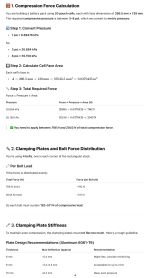
Either way, just for the laughs, I employed our favorite bot for help:

1749476338336.png


With the cited figures, we also get:

  • Suggested Bolts: M6 or M8 with torque control
  • Plate Material & Thickness:
    • Aluminum: ≥8 mm (preferred), or 6 mm + ribs
    • Steel: ≥4 mm
That's way more than I initially expected.
 
I've been reading older threads, and noted someone with an idea similar to mine, which was to pump the battery to about 8psi with air, mostly as a way to stop saltwater leaks in that case. But now I'm thinking, wouldn't that work to compress the cells as well?
The only thing that will compress the cells correctly is to apply the pressure on the ends of the stack, across the largest face of the cells. This keeps all the layers inside pressed together as designed.

Applying a uniform pressure to the entire cell doesn't do that job, as it also pushes on the short faces which is the edges of those layers.

You could pressurize the entire battery case, but you'd want to do that *in addition* to the stack compression, rather than instead of.

Without compression, the cells can develop gas between layers, pushing them apart, increasing resistance, decreasing capacity and current capability, creating random damage to structures inside, etc.

The problems generally are worse with cells that haven't been carefully handled and have been folded or bent or dented, or used at or beyond their capabilities. Greater discharge or charge currents increase the likelihood, as does charging closer to full or discharging closer to empty.


Maybe if the pouches aren't airtight that's not a great idea because the air would enter them like it does with lungs and negate the effect, but that still leaves the possibility of having a "bladder" in the battery acting like a piston/spring.
If the pouches aren't airtight, they've ruptured and should be discarded. ;)

Same for if they've swelled up or are bent up, etc; this damages the layers and makes them not operate as designed, higher resistance, more chance of internal failures, etc.
 
Back
Top