
Right, there will be one of those too, but the FET gate drivers, PWM chip and commutator all run on 14v. 12v would be fine. In the normal application, there is a linear regulator to drop the battery voltage down to 14v, then the 7805 drops it down to 5v for the throttle and and some of the voltage references.
You are using an out of date browser. It may not display this or other websites correctly.
You should upgrade or use an alternative browser.
You should upgrade or use an alternative browser.
Crystalyte Controllers - Repair and Modification information
- Thread starter fechter
- Start date
looking at the picture i could not find the diode you are talking about.
can i just connect pin 2 to ground (- terminal of battery)?
can i just connect pin 2 to ground (- terminal of battery)?
fechter said:ejonesss said:The7 said:The original 48V IS controller has an LVC at 29V.
The 33k and the R6(5.1k) will be removed to de-activate the LVC so that the controller will work from 24V battery to 48V battery for my AL1020 ebike.
i was wondering can the lvc be bypassed all together to allow 12 volt operation or even use of ni cads (witch has no problems with over discharging in fact requires complete discharging to prevent memory) just by jumping a wire from the bat+ to the resistor/diode junction? (basically shorting out both resistors)?
Yikes! don't do that.
If you want to disable the LVC, you could disconnect either the diode or disconnect R6, whichever is easier.
12v might be pushing it since the voltage regulator is trying to make about 14v and needs a little more than that for voltage drop. It might work however. For 12v only, you could possibly bypass the voltage regulator.
ejonesss said:looking at the picture i could not find the diode you are talking about.
can i just connect pin 2 to ground (- terminal of battery)?
No, that will disable the current limiter too.
I think the diode is on the bottom or something. Just remove R6.
what about applying the 29 volt lvc hack to the 300k resistor (looks like 1 volt per k of resistance so in theory it shourl be 9 or 10 volts )
the thing is the controller is still under warranty until november (witch fall will kick in and the weather will be too cold to ride).
if i can just jumper a resistor i can make a jumper on 2 alligator clips that i can clip onto the resistor and once the tests are done i can remove the clips and electricrider.com should not be able to detect tampering if anything goes wrong.
i did apply the abs wire for the regen so i can try out the regen braking and i simply took a piece of wire and poked it into the abs hole and did not solder it so if the controller fails requiring warranty work i can just pull the wire out and electricrider should not void the warranty.
at $250 a piece i would like to not have to pay a $75 diagnostic fee+ any repairs.
i want to find out how low i can take the voltage and still have hill climbing power because with lifepo4 batteries being so expensive i maybe able to trade off voltage for more amp hours.
Yep, that should work.ejonesss said:what about applying the 29 volt lvc hack to the 300k resistor (looks like 1 volt per k of resistance so in theory it shourl be 9 or 10 volts )
fechter said:Yep, that should work.ejonesss said:what about applying the 29 volt lvc hack to the 300k resistor (looks like 1 volt per k of resistance so in theory it shourl be 9 or 10 volts )
i just opened up the controller and i just realized it is version 2 looks like the one
http://endless-sphere.com/forums/viewtopic.php?f=2&t=764&st=0&sk=t&sd=a&start=210
and
http://endless-sphere.com/forums/download/file.php?id=11553
if the picture does not load then copy and paste to view it
witch means the chip is surface mount and the resistors are not along the edge of the board making warranty voidless work more difficult so i guess i will have to bite the proverbial bullet and hope electric rider does not actually open up the controllers or it does not fail requiring repair.
a final update:
it turns out that disabling or lowering the lvc to allow running on 24 volts or even 12 is not going to work.
you lose torque and speed on the lower voltages. so for me at least i will have to put out the $700+ for the 48v 20ah lifepo4 battery.
however there may be still a good reason to lower the lvc would be if you want to get started in electric biking and the dealer does not have a specific controller and you are forced to have to buy a 7248 controller for example but you dont want 6 batteries you can lower or disable the lvc and run it from 48.
rkosiorek
100 kW
there is a separate thread for the V2 controller. it uses a switching regulator to drop the battery voltage down to 15V to run the FETs and drivers.
this regulator is made from discrete components and the schematic for it is on page 1 of the V2 controller thread.
http://endless-sphere.com/forums/viewtopic.php?f=2&t=3896&start=0#p57595
just for a lark i hooked it up to a lab supply and scope. i found that the 15V switching regulator would stop working at around 16-17V so the lower limit of this controller is 17V if this regulator circuit remains. if you do want to use it at 12V this regulator would have to be bypassed. the question remains how llow a voltage will the FETs and drivers switch at. remember that a 12V nominal battery will sag to less than 9V under heavy load. will the controller still work there? i have some doubts and reservations.
The LVC circuit is about halfway down page 2.
http://endless-sphere.com/forums/viewtopic.php?f=2&t=3896&st=0&sk=t&sd=a&start=15#p58887
if you want to lower the LVC down to 17V just change R15 to 3.9K
hope this helps.
rkosiorek
100 kW
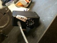
back on page 1 fechter posted a circuit to allow you to adjust the current limit between 20% and 10% of the upper limit set by the shunt circuit.
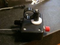
i put one together and put it into a plastic box with a clip to mount it on the handle bar. i put the contol pot on the rear panel. on the front i have a NC pushbutton switch. the switch is just wired in series with the wiper. so normaly the wiper would be connected through a 150K series resistor to pin 1 of the PWM chip, just like in the schematic. so normaly the current limit is set by the control knob. when i push the buton however the control is disconnected and the full power set by the shunt is available.
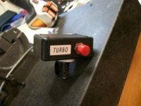
works sort of like a TURBO switch whan i need full power for a few seconds. having it mounted on the handlebar within reach of my thumb just makes it so conveneint.
i put one together and put it into a plastic box with a clip to mount it on the handle bar. i put the contol pot on the rear panel. on the front i have a NC pushbutton switch. the switch is just wired in series with the wiper. so normaly the wiper would be connected through a 150K series resistor to pin 1 of the PWM chip, just like in the schematic. so normaly the current limit is set by the control knob. when i push the buton however the control is disconnected and the full power set by the shunt is available.
works sort of like a TURBO switch whan i need full power for a few seconds. having it mounted on the handlebar within reach of my thumb just makes it so conveneint.
Attachments
marty
10 MW
Question about heat? Got Crystalyte 36V 35A Start Immediate Analog Controller. Using 48V battery. Took it out of case. See Fechter's picture.

Note the white thermal joint compound between aluminum block and aluminum case. Been testing with bike mounted in stand. Do not notice controller getting hot or warm. Plan on putting controller in new water proof box. Do I need to worry about heat? Should aluminum block be mounted tight to new aluminum case with thermal joint compound? Or can I use a plastic case and not worry about heat?
Note the white thermal joint compound between aluminum block and aluminum case. Been testing with bike mounted in stand. Do not notice controller getting hot or warm. Plan on putting controller in new water proof box. Do I need to worry about heat? Should aluminum block be mounted tight to new aluminum case with thermal joint compound? Or can I use a plastic case and not worry about heat?
On a stand, the motor does not draw enough current to make much heat. On the road is another story. The heat is significant and needs to go somewhere.
An aluminum box would be ideal. Another approach would be a plastic box with a large square hole cut in one side where you can mount an aluminum plate. The plate can be sealed to the box around the edge to make it waterproof, but have the aluminum exposed to the air for cooling. Attach the controller block to the inside of the plate. If you attached some cooling fins, size of the plate could be reduced. The block itself could be used for the plate if you can get all the heat sink goop off good enough for glue to stick to it and you plug all the holes with silicone.
An aluminum box would be ideal. Another approach would be a plastic box with a large square hole cut in one side where you can mount an aluminum plate. The plate can be sealed to the box around the edge to make it waterproof, but have the aluminum exposed to the air for cooling. Attach the controller block to the inside of the plate. If you attached some cooling fins, size of the plate could be reduced. The block itself could be used for the plate if you can get all the heat sink goop off good enough for glue to stick to it and you plug all the holes with silicone.
marty
10 MW
Thanks Fechter,
The new water proof controller box will be aluminum. Thinking about a air vent so it will dry out if water does gets in.


The new water proof controller box will be aluminum. Thinking about a air vent so it will dry out if water does gets in.
Similar threads
- Replies
- 5
- Views
- 3,171
- Replies
- 10
- Views
- 2,508

- Replies
- 189
- Views
- 20,376
- Replies
- 441
- Views
- 73,982