nieles said:
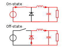
the diode cant be in stead of a capacitor right? looking at the picture below, so i added beteween C of Q1 and GND
Yes, entirely correct and a stupid mistake on my part. Glad at least one of us is paying attention.
")
It sounds like we're making progress.
Am I correct that I see a bit of oscillation in those scope plots? It looks a little more prominent in the first set, with the 50R inductor and less so with the 0R2 inductor. Are these plots of collector voltage that you're showing us? I'm seeing some similar effects showing up in SPICE simulations. It doesn't really seem to affect the circuit much, but I'm looking to try and isolate exactly the source and make some slight changes to eliminate it if possible. I'm trying to figure out exactly what rev 2.0 of this circuit should look like. The changes I'm looking at are probably things that we don't need to worry about hacking this one for, just little improvements for the next version.
Also, how you attached a flux ring to the sensor board, yet? I put that huge U-cutout in the interface board to make sure it doesn't interfere with the flux ring. But if we don't need the cutout, I can gain back a lot of board real estate that would make the layout easier, and also use more copper area to heatsink the regulator. Just something to think about as we're making lists of what to change.


.jpg")
.jpg")

.jpg")
.jpg")


