Current Controller for RC ESCs

Aaaaagh gotcha cheers, and yes that's what I recalled Luke said about the throttle interface gizmos that limited battery current being worse than no limiting.

KiM
 
parabellum said:
Nieles, what hall sensors will be used or better what current range can be used on this test batch?

rhitee05 said:
Here's the feature set for the prototype:
- Custom hall-based 3-phase current sensor. The sensor should have fully-linear range of >300A, >200A, or >150A depending on the sensitivity of the sensors used. Sensor is fully isolated and insulated from the phase wires - the current design just has 3 0.25" dia holes which the phase wires pass through. I have some 8 ga wire which passes through easily.
- Interfaces to standard 5V e-bike throttle, hall- or pot-based. 5V supply is provided to the throttle. Currently both gain and offset adjustments are included.
- Option for either pass-thru throttle or closed-loop current-based throttle (selectable by jumper).
- Throttle filtering with separate up/down ramp times if desired (ramp-down time <= ramp-up time). Filtering can be disabled by removal of a capacitor.
- Option for throttle "boost" which provides temporary 10-30% (set by fixed resistor) increase in throttle gain. Boost is activated by a momentary pushbutton.
- Phase current limiting via 2 separate limits (works for either direct or closed-loop throttle). One limit has a fast, aggressive response, the second has a slower, integrating response which is less aggressive.
- Includes servo interface directly to ESC with adjustable min/max pulsewidths. Pulse rate is set via a fixed resistor (50 Hz nominal). Prototype is designed to drive ESCs only, but future versions will have a 0-5V output to drive a standard controller instead.
- Current design generates 5V supply directly from the battery. Future versions will probably make that optional, either internal 5V supply or taken from an external BEC, and will probably use a switching regulator rather than the current linear regulator.

based on the features rhitee05 posted:

300A with a 2.5mV/G hall sensor (original allergro A1321)
200A with a 3.125mV/G hall sensor (original allergro A1322)
150A with a 5mV/G hall sensor (original allergro A1323)

i will be using a honeywell part, because mouser doesnt stock the allegro halls
so ss495a with 3.125mV/G (200A)
or ss496a with 2.5mV/G (300A)
 
LOL, I was just about to copy-paste the same text that nieles just posted. Great minds! From my perspective, the advantages of this unit over the RC-CA would be that it's a cheaper, single-purpose solution. It measures phase current directly for limiting, rather than extrapolating from battery current. I tried to put in a variety of places where it can be tweaked for various users, but the tweaks will be either pot adjustments or in some cases de-soldering and replacing a component, rather than adjustments in software. The tradeoff for being cheaper is fewer bells and whistles. It should also be a fairly small package. I think the board stackup should end up being something like 5 x 5 x 3 cm.

As far as current ranges go, I think for the 2.5 mV/G sensor it should end up being something like 320 A in the fully linear range, and possibly as high as 640 A in a "less-linear" range. It depends on how close the hall sensors behave to my FEMM model.

I'm trying to put together a quickie documentation package for nieles to work off of. I think I can scrape some time together over the weekend, and I would still love to see this come to fruition even if I'm handing it off to others in the community. I'm sure even a quick-and-dirty documentation from me will decrease his workload significantly.

I'm glad to hear his estimate of $60/ea for small quantities. My goal when I designed this was to keep it fairly cheap, and I was guessing the BOM would come somewhere in the $50-$75 range.
 
Eric,
Thanks for the continued support on this little project. I have pmed Nieles & am waiting to hear what his schedual is....

I have a new fightercat sensorless controller here good for 16cells ready for some serious testing.
if this limiter works as planned it will be a huge boone to the rc crowd....or the sensorless crowd in general. I know a CChv160 is not a cheap controller....but in side by side testing....it will destroy a 12fet xiechang controller in acceleration & performance.

I assume the current limiter will take some of the edge off the lil' neck breaker, but i have high hopes. :mrgreen:
 
Thud said:
Eric,
Thanks for the continued support on this little project. I have pmed Nieles & am waiting to hear what his schedual is....

I have a new fightercat sensorless controller here good for 16cells ready for some serious testing.
if this limiter works as planned it will be a huge boone to the rc crowd....or the sensorless crowd in general. I know a CChv160 is not a cheap controller....but in side by side testing....it will destroy a 12fet xiechang controller in acceleration & performance.

I assume the current limiter will take some of the edge off the lil' neck breaker, but i have high hopes. :mrgreen:

it is a little premature for me to say, but i am not sure the 5v regulator will work with 16cells. but i am sure we can get it working with an external 5v BEC (could be as simple as using a 5v phone charger on DC) i am using a 12v AC wall adapter with an 20s pack for an other application and it works perfecly.

i am looking for alternatives for a few parts. i am planning to order everything late next week.


i cant stop smiling when looking at the board layout. it is so well thought out with the 3 stacked boards. big thumbs up to you eric!
 
Nieles is right to be cautious about the voltage regulator for 16s. When I designed it, I was mainly thinking about <50 V as the usual range for RC ESC's. However, I think it probably would not be a major issue. The PNP transistor I specified should be fine at that voltage. If there is an issue, it would be heat. You'd have to test it to find out.

I'll also point out, regarding the BOM, that not all of the parts on the board are intended to be populated. There are several places where I put components on the layout for "just in case" and several places where the intention was to place either component A or component B, but not both. All that will be explained in the documentation.

I'm glad you like the layout. I just hope you aren't cursing me under your breath while you're soldering SMT components... You might've also noticed that there's a mixture of SMT and thru-hole components. I was trying to be nice to future users, so that I used thru-hole for components I anticipate might need to be changed to enable a feature or to tweak a parameter.
 
rhitee05 said:
I'll also point out, regarding the BOM, that not all of the parts on the board are intended to be populated. There are several places where I put components on the layout for "just in case" and several places where the intention was to place either component A or component B, but not both. All that will be explained in the documentation.

I'm glad you like the layout. I just hope you aren't cursing me under your breath while you're soldering SMT components... You might've also noticed that there's a mixture of SMT and thru-hole components. I was trying to be nice to future users, so that I used thru-hole for components I anticipate might need to be changed to enable a feature or to tweak a parameter.
Thanks Eric & alpha-beta testers for continuing to provide some support here with documentation & ideas & dev. I wish I had the ability to help out but can only standby for testing after initial prototypes prove to work.

This is a long needed device (years of deprivation & fried Esc's.) :shock:
 
Yikes.. I stopped getting notifications for this thread.

Thanks for all your work on this Eric.

Thanks for taking it on, Niels.

Count me in for Alpha testing, if it's not too late.
 
Please keep on developing! I'm a poor student, but five or 10 bucks would be ok for me (I already translatet patents for less ;) ) if you write a documentation and upload an image pcb.

Next year I could make use of it when my next bike is ready. It has a T-80-100 KV130 and ATM I'm testing my config with a 6-FET stock controller which did at least can't blow :mrgreen:

I don't ever want to blow a controller in my live (don't bet on me :D )
 
crossbreak said:
Please keep on developing! I'm a poor student, but five or 10 bucks would be ok for me (I already translatet patents for less ;) ) if you write a documentation and upload an image pcb.

Next year I could make use of it when my next bike is ready. It has a T-80-100 KV130 and ATM I'm testing my config with a 6-FET stock controller which did at least can't blow :mrgreen:

I don't ever want to blow a controller in my live (don't bet on me :D )

I would immediately stop using a 6 fet stock controller then... i popped a modded 12fet 20 feet out my driveway on
a Turnigy 80-100 130Kv...twice!

KiM
 
You all remember the esc controller from the colossus thread. We intended to use this for Colossus 12kw , then we decided to go sensored . I am sorry to see struggle to find appropriate controller. I want to help so here is the help : http://www.hifei.com/en/index.asp ......Hifei manufacturers most of the strongest powerfull escs on the market so maybe it helps and they had this giant esc intended for paragliding motors.... Somebody should contact them in the name of ES and check it ....Cant help with anything else since i dont have tech know-how for esc .. Keep up with great work
 
sorry for not posting an update on this thread earlier, but i have been a bit busy.

The boards are ordered and i expect to recieve them next week.

i also ordered all the needed parts form mouser. these should be delivered this week.

my plan is to first make 1 set of boards complete and make sure everything works,
after that i will build the alpha testing units. my plan is to do 3-5.

Niels
 
hehe, I was Just going to bump this thread.
I assume you got the PP Nieles? Also I have a few flux rings for you..PM me a mailing address & I'll send em off to you this week.

Looking foward to seeing some test data.
thanks.
T
 
yes thank you thud! you will get the first Test unit as soon as i have a working unit.
will send you a PM with my adress.

i will see if i can get some flux rings lasercut for future units.
eric, will it matter that the material for the flux rings is 3mm instead of 1/8 inch (3.175mm)?
 
nieles said:
i will see if i can get some flux rings lasercut for future units.
eric, will it matter that the material for the flux rings is 3mm instead of 1/8 inch (3.175mm)?

No, 3 mm is fine. I believe the Hall sensors are 3 mm high, so it should not be any thinner than that but the exact thickness is not very important. I believe the actual sensor element is <1 mm wide inside the package. At one point I looked into getting some rings laser- or waterjet-cut from places online, but the setup costs were prohibitive to make just a few. It would probably be economical as part of a small production run, though. The specific alloy should not be important, either. I believe the characteristics of any low-carbon alloy should be similar enough to use.
 
last night the last order came in, and started soldering on the first PCB.

after soldering the 0603 Resistor Arrays, the other parts are easy to solder :shock: :mrgreen:
i will see if i can fit the Resistor Arrays with an 0805 Package, should make the soldering a bit easier


in the weekend i will do some testing, and then proceed with the alpha test devices

Niels
 
That's cool

It's so good that this project is still alive!!!!

Thanks Eric, Niels, Thud and anyone supporting it...

Jules
 
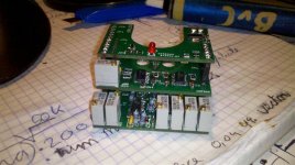
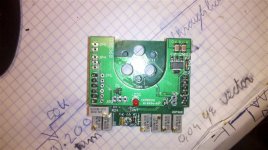
minus the Flux ring the first current controller is Ready for testing
View attachment 2
2011-11-11_19-45-08_607.jpg
2011-11-11_19-45-22_168.jpg

Measuring 5cm*5cm*3cm (not counting the LED) its a real beauty if i say so my self 8)

Next: Testing Basic functionality and see if i can make a flux ring if i can find some material for it

Niels
 
oops,
Nieels, I'll send you some flux rings tomorrow....(no mail today national holiday) i completly forgot these!
sorry to hold you up. :oops:
T
 
Very pretty! Glad to see everything worked out with the layout (not that everything I make isn't perfect on the first try... :oops: ).

For initial testing, you might start by just applying an input voltage directly to the pad where the hall output connects, one sensor at a time, and check all signal at various intermediate points.

It just occurred to me, though, that the neat stacked design could make it a pain in the @$$ to look at the signals on the inner boards. One of the stacking headers carries all the signals, so you could probably rig a ribbon cable or something to let you un-stack the boards for testing. You just need to hook up one of the pins on the second header to tie the grounds together.
 
Back
Top