Cycle Analyst V3 preview and first beta release

wannesd said:
I can't decide whether to buy the CA V2 or V3, as I would need it in 2 weeks time.
Any updates as to when the v3 would become available?
If you are reading thru this thread, you should note that it hasnt' even finished beta, and now is on hold till Justin is recovered, so I can't imagine it being avaialble in time. You'd have to check directly with Grin Tech to be sure, though.

Personally, I'd hold off till it *is* available, if you need those features. If you don't, then there is no reason to wait at all.
 
Justin, I tested all the ground on the cycle analyst and found that they are all common, including the ground for the V aux input.

So if someone have a let say 400V pack, a C-A and a DC-DC to supply it with the 12V out from the dc-dc, and connect it with resistor divider to that Aux input with the 400V battery , that mean that the 12V ground and the 400V ground will be linked ? :eek: so the dc-dc will lost his insolation advantage.

wich way would you suggest to use this Aux V input and keeping the HV and 12V isolated ?

mayube using a little DC-DC just for supplying the C-A board?


But in this case, all the other I/O of the C-A will be linked to the HV thru their ground..

I searched for this info and i did not found the answer

Thanks Justin! ( btw, please could you re-upload your last youtube video, it is incomplete )

Doc
 
What is the problem (or potential problem) that you see with having the low-voltage and high-voltage grounds linked together?
 
Interesting. I've no experience with electric cars, but in the world of broadcast transmitters we typically reference everything to chassis, including the 10-15kv plate supply used in the larger tube-type models (yes, we still use tubes.) Admittedly, transmitters are not intended to be occupied while in operation, and this can make for some interesting pyrotechnics when something goes fruity. :mrgreen:

Assuming you want the CA to be able to monitor battery voltage, there's really no easy way around having the grounds common. The same issue arises in the fact that the CA's throttle output voltage is also referenced to its own ground, and presumably the controller to which it will be connected does not segregate the battery's (-) terminal from its own internal logic ground either. (The controller needs to see the CA's ground in order to receive the throttle signal from the CA.)

I suppose you could use a very low-current polyfuse to bridge the two grounds if safety is a concern. Both the CA's VAUX input and the controller's throttle input should be quite high-impedance, so not a lot of current is going to be flowing between them. This will minimize the effect of whatever minuscule resistance exists across the fuse.
 
Doctorbass said:
So if someone have a let say 400V pack, a C-A and a DC-DC to supply it with the 12V out from the dc-dc, and connect it with resistor divider to that Aux input with the 400V battery , that mean that the 12V ground and the 400V ground will be linked ? :eek: so the dc-dc will lost his isolation advantage.

which way would you suggest to use this Aux V input and keeping the HV and 12V isolated ?

maybe using a little DC-DC just for supplying the C-A board?

Joe Perez said:
What is the problem (or potential problem) that you see with having the low-voltage and high-voltage grounds linked together?
I think it's not acceptable usually for safety.
Doc
First, to be clear, your link is referring to automobiles with a live chassis ground. In the case of an ebike, there is no good reason to use a grounded frame, so the 12v lighting etc is (should be) already isolated from the frame and the dangers of joining the motor and battery grounds are substantially reduced. However, sidestepping a discussion of the 'why' in favor of your wish to keep the vehicle Vbatt isolated from the 12v utility power:

We assume that the Vaux and throttle are being driven with the on-board CA +5v supply (as intended) and accept that various CA inputs will share a ground with the high voltage vehicle Vbatt. This is inescapable by the CA design and without a -Vbatt tie to chassis ground, the dangers appear minimal or at least manageable.

Justin indicates that the internal CA v3 electronics draw about 10ma. Assuming a resistive throttle of about 5K and a resistive Vaux divider of about the same resistance, then we are looking at 5v/5K + 5v/5K = 2ma for a total of 12ma. For a 12v CA power source, the on-board regulator will need to dissipate (12v-5v)*12ma = 84mw, well below the device limit of 1500mw.

The easiest solution is simply to tap the vehicle battery to drive the CA with around 12v. The low 12ma draw is not going to materially unbalance the affected cells and this would leave the existing 12v supply unused and unaffected.

Otherwise, your suggestion to provide a second voltage supply dedicated to the CA seems a good approach. To avoid the large power dissipation to drop Vbatt (400v in your example) to the allowable CA supply voltage, and to take advantage of the very low current requirement (around 12ma above), a good solution might be to use an isolated DC/DC converter component module to provide 12v from the existing available 12v supply. These are available for $10 or less on eBay ('Isolated DC Converter 12V'). The 12v module output will then power the CA and share the vehicle Vbatt ground while the primary utility 12v supply will remain isolated.

EDIT - Authoritative answer from Justin can be found here.
 
Justin, is the std TTL/USB cable for the CA data logger the same as the one that is used for firmware updating of the V3?

I have tried to order one to bring my V3 upto date but when directed from ebikes.ca to PP the postage is not added so i didnt complete the order, or are they on free post :D and i should have gone ahead and completed it?

Or is this something i could quickly knock up myself from a usb lead?

Simon.
 
AWESOME FEATURE REQUEST:

Separate shunt input that Monitors charging cycles so that cycle analyst always has an accurate measurement of SOC (within 1%) For example, if I simply want to bulk charge with a small charger in a parking garage but I do not know when I will be back to the bike, the cycle analyst will simply subtract the Wh charged from the Wh used, without affecting the Wh/mile figure, etc. displaying Ah remaining versus used I think would be more intuitive. I'm many pages behind, so sorry if I'm being redundant.

My condolences...
 
Tench said:
Justin, is the std TTL/USB cable for the CA data logger the same as the one that is used for firmware updating of the V3?

I have tried to order one to bring my V3 upto date but when directed from ebikes.ca to PP the postage is not added so i didnt complete the order, or are they on free post :D and i should have gone ahead and completed it?

Or is this something i could quickly knock up myself from a usb lead?

Simon.
Justin may not yet be monitoring this thread, so an email to ebikes.ca will likely get you a faster response to specific questions, but no promises... Here's a best effort answer:

My Analogger came (this month) with three data cables:
  1. an off-the-shelf USB-A to mini-USB-A cable that plugged into the matching jack on the Analogger proper,
  2. an off-the-shelf straight-thru 3.5mm to 3.5mm audio extender cable to interconnect the CA Tx/Gnd to the Analogger Rx/Gnd (the actual Tx/Rx crossover occurs on the Analogger board not in the cable), and
  3. a two wire female dongle cable (3.5mm audio jack) to be soldered to the CA board at Tx/Gnd.
By comparison, the CA v3 programming cable appears to have an embedded (USB)->(5v RS-232) converter chip. It has a male USB-A connector on one end and a 3.5mm stereo audio plug on the other. A matching three wire female dongle cable (3.5mm audio jack) is provided to be soldered to the CA board at Tx/Rx/Gnd. This is a compatible upgrade to the two wire dongle provided for CA->Analogger communication and affords the extra Rx connection for bidirectional comms with the downloader app.

So - the Analogger uses standard cables but the CA programming cable is not something you can easily cobble together and the supplied CA female 3.5mm dongles differ. The USB/RS232 converter cable and dongle can be sourced elsewhere, but supporting ebikes.ca seems appropriate. :)

EDIT - Authoritative answer from Justin can be found here.
 
Thank you for that Teklektik, it confirms that there is adifference and i do need to order the specific V3 TTL cable from ebikes.ca
 
16 june: PROBLEM SOLVED... it was a stupid thing.. the sensor was not close enough to the motor and one of the notch on the axel was making double pulse . The speed reading is not OK :mrgreen:


Maybe someone already know the answer to this question:

I've installed my new V3 C-A on my brand new Zero DS 2011 Electric motorcycle and everything work great!!! except for the speed reading.

Instead of using the classical magnet and magnetic sensor, i prefered using the tach optical signal from the Agni motor pulley.

Problem is that this signal is pulsed from 0-3V ( there is 3 wires. A GND, a 5V and the signal)

The C-A is specified to accept 0-5V, 0-12v and float to gnd. But it seem to not work with 0-3V.

What I don’t really understand is that when the motorcycle was I my garage on a stand to test it with the rear wheel free, the speed reading was OK and match according to the calibration I made with the original zero gauges. But once I have put it on the road for test, the speed on the C-A was really low but was nearly proportional. Just like if there is a ratio…

The only thing I think it could affect the reading is the high current in the battery and motor wires that are close to al the rest of the signal wires.. but these wires are shielded and great quality including the one I used to cary the signal to the C-A.. and all shield are connected too.

Any idea about how the speed signal work ?.. I guesss there is a pull up or pull down resistor somewhere that I could modify ?

Thanks
Doc
 
You could use a simple transistor booster, with a 2n2222 or similar, only need the transistor and a series base resistor. Drive the base resistor with the 0-3V signal, then use the transistor hooked up collector to speed signal in as if it was a reed-type sensor, and emitter to ground.
 
Doctorbass said:
Problem is that this signal is pulsed from 0-3V ( there is 3 wires. A GND, a 5V and the signal)

The C-A is specified to accept 0-5V, 0-12v and float to gnd.
To digress a bit from discussing your issue - did you get this spec from ebikes.ca for the v3? The 0-12v is neat but a little surprising... (Just collecting/verifying little bits of v3 knowledge :) )

Sidestepping the different behavior on the stand and on the road for a moment (this may be an important clue, but no bells are ringing for me...):

It sounds as if you have made efforts to eliminate noise leaving the most likely culprits to be issues with the voltage or the pulse shape. 3v is a bit more than marginally a logic 'high' signal (assuming that other analog thresholding is not in play) so I'm wondering about the pulse duration. Since the motor speed is slow in electronic terms and the failure is not speed-related, it doesn't sound like a rise time or pulse shape issue where the pulse might not reach the full 3v in the allotted time at higher speeds - so....

Is the optical sensor on your bike giving you a +3v pulse or a ground-level pulse? Just guessing here, but he CA software has windowing/debounce logic to condition the signal and this might be confused if you are giving it an inverted signal with a +3v pulse because the relative on/off times will be reversed. If so, the transistor inverter described by amberwolf would likely fix the issue by translating the +3v pulse into a ground-level pulse (or any similar inverting gimmick you can cobble together from available parts e.g. op amp, 555 timer, opto-isolator).

...just a thought...
 
Big thanks for the suggestion guys :wink: :mrgreen: , Problem solved!.. please read the comment i added.

Doc
 
AWESOME FEATURE REQUEST:

Separate shunt input that Monitors charging cycles so that cycle analyst always has an accurate measurement of SOC (within 1%) For example, if I simply want to bulk charge with a small charger in a parking garage but I do not know when I will be back to the bike, the cycle analyst will simply subtract the Wh charged from the Wh used, without affecting the Wh/mile figure, etc. displaying Ah remaining versus used I think would be more intuitive. I'm many pages behind, so sorry if I'm being redundant.

If the negative lead of the charger is connected to the load side of the current shunt inside the controller, and the cycle analyst is turned on when charging, then the charging current will be sensed and the Ah display will show correctly the state of charge.

Justin,

Can we get controllers that have been modified with a charger negative lead from the factory?

Thanks loads for making the CA tolerate mis-connections of sensors without damage.
CA-3 is awesome.

Waldo
 
Waldo said:
hillzofvalp said:
AWESOME FEATURE REQUEST:
Separate shunt input that Monitors charging cycles so that cycle analyst always has an accurate measurement of SOC (within 1%) For example, if I simply want to bulk charge with a small charger in a parking garage but I do not know when I will be back to the bike, the cycle analyst will simply subtract the Wh charged from the Wh used, without affecting the Wh/mile figure, etc. displaying Ah remaining versus used I think would be more intuitive.
If the negative lead of the charger is connected to the load side of the current shunt inside the controller, and the cycle analyst is turned on when charging, then the charging current will be sensed and the Ah display will show correctly the state of charge.
hillzofvalp said:
Only problem with doing that is that I would lose my Ah statistics.
From a hardware perspective this seems spot on, Waldo. This appears to be a sensible approach to achieve 95% of the value of the feature request without adding extra CA hardware to monitor a dedicated 'charging shunt'. Loss of the running Wh calculations does not seem too punishing. Simply starting with a CA-SA instead of a CA-DP(S) is a easy way to implement the necessary connections without modifying the controller (for 45-50A or less).

CA-DP-SA_v3.gif
However, this still leaves the nagging question of accommodating the charging efficiency of the battery since not every Ah going in is stored as usable power. Although the CA v3 does know the general battery chemistry, added complications are the pack temperature as well as the possibility (in the general case) of accumulated errors from multiple partial charge/discharge cycles. Inaccuracies due to these factors can lead to incorrectly perceived SOC, although the LVC will still avoid battery damage for balanced packs (i.e. battery safety is not in question - just operator surprise :D). This matter of charging (not charger) efficiency deserves comment by Justin or someone with more specific working knowledge of various cell-level chemistries than I possess :wink:.

Perhaps I am too conservative, but my knee-jerk reaction is that this seems more like a 'known user hack workable with caveats' than a reliable supported product feature yielding clear business benefit...
 
Well, Kay.

But it could be pretty accurate especially if it's calibrated every time a charger kicks off at say 90% soc, which would probably be every other charge in most cases unless you're a delivery man. The temperature would be fairly constant with a cheap 200-400Wcharger for most packs I would think.

I suppose the cell level voltage curves in the new ca could be fairly accurate.

If my charger is outputting at say 400W (at the output leads), doesn't 398W-400W get applied to charging the battery especially for high c-rate packs being charged around .5-1C? I don't know enough about charging losses either.
 
teklektik said:
Tench said:
Justin, is the std TTL/USB cable for the CA data logger the same as the one that is used for firmware updating of the V3?
I have tried to order one to bring my V3 upto date but when directed from ebikes.ca to PP the postage is not added so i didnt complete the order, or are they on free post :D and i should have gone ahead and completed it?
Or is this something i could quickly knock up myself from a usb lead?

Simon.
Justin may not yet be monitoring this thread, so an email to ebikes.ca will likely get you a faster response to specific questions, but no promises... Here's a best effort answer:

So - the Analogger uses standard cables but the CA programming cable is not something you can easily cobble together and the supplied CA female 3.5mm dongles differ. The USB/RS232 converter cable and dongle can be sourced elsewhere, but supporting ebikes.ca seems appropriate. :)

Hey everyone, I'm back again. It's possible to use any serial device that has a 0-5V TTL or CMOS output voltage to reprogram the CA. So if you have a programmer cable for infineon motor controllers or what have you then that should work fine. The USB->TTL serial cable that we sell is the TTL-232R-5V-AJ part direct from FTDI which is a bit pricey:
http://www.ftdichip.com/Products/Cables/USBTTLSerial.htm

So if all you need it this it would make most sense to order it direct, no need or or purpose at all in purchasing from us. If people have found and used other USB-> TTL UART cables with success then feel free to post the supply here as well. We haven't done much digging around yet but presumably there are some cheaper sources that could better serve people.

-Justin
 
Thanks Justin, i got your email the other day about this and sourced one locally, its on its way to me.

Simon.
 
Doctorbass said:
Justin, I tested all the ground on the cycle analyst and found that they are all common, including the ground for the V aux input.

So if someone have a let say 400V pack, a C-A and a DC-DC to supply it with the 12V out from the dc-dc, and connect it with resistor divider to that Aux input with the 400V battery , that mean that the 12V ground and the 400V ground will be linked ? :eek: so the dc-dc will lost his insolation advantage.

Yes, this is correct.

wich way would you suggest to use this Aux V input and keeping the HV and 12V isolated ?

We looked into having an isolated external VBatt input but it didn't make sense given how rarely this would get used. You could in principle make a small circuit using a linear opto-isloator like the IL300, and feed the now isolated signal from that into the CA's external voltage sensing pad, and then similarly use a scaled down hall device current sensor for the S+ and S- leads. That would provide the CA with both the voltage info and the amperage info while maintaining isolation with the battery ground.

mayube using a little DC-DC just for supplying the C-A board?

Exactly my main suggestion, if you don't want your vehicle's 12V DC-DC to be ground referenced, then you can either use a small isolating DC-DC off the 12V bus, or a nominal 90-240V AC input adapter off the battery bus. Then your 12V vehicle supply will stay isolated.

But in this case, all the other I/O of the C-A will be linked to the HV thru their ground..

Yes. In the world of ebikes and PEV's every signal in the controller is referenced to the battery ground so this makes sense, but in HV systems things are usually done electrically isolated. Right now, you can consider the CA as a low voltage device that is somewhat "hacked" to work with high voltage systems for those who need it, with some downsides like lack of isolation. If it was designed primarily as a high voltage monitor then we would have done things quite a bit differently.

-Justin
 
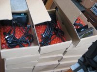
Hey everyone, while I was away there was still a bunch of activity here at the shop and the 50 pcs pilot batch that I alluded to some time ago got completed last week, thanks largely to Michael and Mark. Here's the proof ;)

Mr Vass with Pilot CA Rework.jpg

V3 CA Pilot Run.jpg

These have all the auxilliary function wiring complete. We're still going through programming and calibration but expect they should start to ship in a day or two. There will also be a Beta15 version of the code to go with it that fully implements the battery fuel gauge SOC algorithm, which I'll post here as well so people can finally have their little battery glyph display more meaningfully.

Is now too early for you to give us a time and price estimate for this V3 CA?

The pilot (still beta) devices above will be $160 each. We're still scrambling with a few of the parts supplies but seem on schedule to have everything in place for full production in 1st-2nd week of July. We're also expecting our bulk order of THUN torque sensors by early next week.

-Justin
 
justin_le said:
... We're still scrambling with a few of the parts supplies but seem on schedule to have everything in place for full production in 1st-2nd week of July. We're also expecting our bulk order of THUN torque sensors by early next week.
-Justin
Excellent!
 
Back
Top