Cycle Analyst V3 preview and first beta release

teklektik said:
Looking forward to your beta test announcement :)

OK, well we just replaced all the microchips on all the beta boards with a new device having twice the memory. So we should be able to add pretty much all of the features that have been discussed here without running into the space limitation at least for quite a while. We still need to do the conformal coating and final assembly so they should be able to ship shortly after the easter weekend.

The purchasing page is live right here:
http://www.ebikes.ca/store/store_CAV3.php

I'll have photos and a bit more details put up in the next day or two.

Just note that these units do not have any of the new accessory features pre-wired. So you will need to open them up and solder cables to the PCB to use the throttle input, aux input, temperature probe, PAS sensor, ebrake cutoff etc. as required for what you want to use. That is part of why the price is lower than earlier suggested. In about 3-4 weeks, we'll have a pilot batch made up that does include a cable assembly bringing all these things out of the enclosure like this:


So for people less keen or comfortable doing board soldering, it would be wise to wait for the pilot batch. -Justin
 
justin_le said:
The purchasing page is live right here:
http://www.ebikes.ca/store/store_CAV3.php

I jump in it! :lol: Order in, I can't wait to drop this on the Norco and try a bazillion things. Hope production goes smoothly! :D

-JD
 
I am in as well! Can't wait to push my bike to the limit... at least with this version 3 I will know where the limits are!
 
This is getting closer and closer to what I want to do to control my bikes, although the way I would likely use some of the features would be different than most. :)

Doing any trade-ins? :lol: I expect not--wouldn't make sense financially to end up with a bunch of used CAs to resell.
 
This is fantastic Justin. I cant wait to get one. Thank you for constantly delivering what the world needs my friend.
 
johnrobholmes said:
Wow, that is a mess of cables! I'm gonna need my 100 pin connector do do all that we want on the new CA :lol:

Yeah, it is a bit of a mess! We are seeing what we can find in the way of a small clamshell enclosure that could have a bunch of wire holes drilled through the sides. That way at the very least we could cover up all the connectors in a tidy box, and keep them away from direct rain exposure.

-Justin
 
Regarding possibly unusual ways to use the features, I have been pondering way to make a torque sensor for the motor wheel itself, perhaps at the dropouts, so I can use the CA to see how much torque is actually being applied at what power levels, with varying loads on the bike. It would be interesting to be able to use that info to be able to limit power of the motor to prevent dropout destruction.

In the case of a middrive thru the bike chain, maybe I could apply that to prevent chain breakage, etc, for when things get misaligned or the chain jumps off. That's what destroyed so many of my chains and chainrings on CrazyBike2's original powerchair drivetrains.
 
Woohoo!! :D got my order in!! cant wait to play with the throttle ramp up rate and be able to dial the do nowt out of the throttle travel without having to have a pot in the throttle wiring.
I have a perky midmount that will benefit no end from the extra control this will give, i shall look forward to reporting on it and contributing with some feed back.
Not to mention the fuel gauge etc, i am going to have to read this whole thread again now to refresh my memory of the new functions!!

Simon.
 
amberwolf said:
Regarding possibly unusual ways to use the features, I have been pondering way to make a torque sensor for the motor wheel itself, perhaps at the dropouts, so I can use the CA to see how much torque is actually being applied at what power levels, with varying loads on the bike. It would be interesting to be able to use that info to be able to limit power of the motor to prevent dropout destruction.

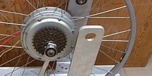
You can totally do this and have the V3 CA measure the motor mechanical power rather than the human power. It would do that similar in principle to my first dyno build: just support the motor axle in a 12mm (or 14mm) ID ball bearing so it can spin freely, and then clamp a solid torque arm to the axle flats with the end of the arm attached to a load cell:
Dynamo Parts.jpg

In this setup, you'd be able to see in real time the motor's instantaneous efficiency by comparing electrical and mechanical watts, and you could see the average motor efficiency over a trip by comparing the accumulated electrical and mechanical watt-hours. It would be pretty nifty. JRH was discussing over email using the CA V3 as the instrument part of a dyno bench which is basically doing the same thing.

In the case of a middrive thru the bike chain, maybe I could apply that to prevent chain breakage, etc, for when things get misaligned or the chain jumps off. That's what destroyed so many of my chains and chainrings on CrazyBike2's original powerchair drivetrains.

You could, although if this is the main goal it would be just as effective and a lot simpler to use a phase current limit on the motor controller rather than trying to measure the motor axle torque directly. But CrazyBike's are about far more than doing things the simple way ;)

-Justin
 
justin_le said:
I had another idea though which might be the best option for systems that have a hard time getting closed-loop current control working smoothly, but that would still have the overall benefits of a current throttle in that the full range of the throttle motion is useful regardless of your speed. This would again require the CA knowing the Kv of the motor in kph/V. The throttle output of the CA would countinously scale upwards with the vehicle speed, such that (based on Kv) the no-throttle motor RPM is slightly less than the RPM of the wheel. Then the throttle motion moves the output voltage above this point.

So in equation format it would be something like:
Throttle Output = K1*(vehicle speed / motor Kv) + K2*(user throttle)

Where the contant K1 would be figured out by the CA from the battery voltage and the throttle output range, while K2 would be a parameter that the user could set. There are a lot of advantages to running open-loop in this manner, since you wouldn't have to tune any feedback parameters and it would better cope with controllers that have response lags and latencies.

-Justin

Hi Justin, has this been implemented in the Beta version?
It crossed my mind that this may be a problem on a midmount using gears, in this instance the CA would need another input of an rpm signal from the motor or controller and could not use the speed signal which would be wheel generated for the throttle signal calculation.

Simon.
 
Amberwolf,

You and I are thinking along similar lines 8) I agree with Justin that it would better to use the phase amp limiting to keep your torque levels in check, but you could at least use a torque sensor at first to test and calibrate where you need phase limits set to prevent destruction.


My idea for on-bike use is to mount the motor on a torque cell and have the ability to calculate real time system efficiency!


I know the feature list is getting quite long in the tooth now, but the ability to set the torque sensor input to "motor" instead of "human" input with automatic efficiency calculations would be over the top!
 
justin_le said:
You can totally do this and have the V3 CA measure the motor mechanical power rather than the human power. It would do that similar in principle to my first dyno build: just support the motor axle in a 12mm (or 14mm) ID ball bearing so it can spin freely, and then clamp a solid torque arm to the axle flats with the end of the arm attached to a load cell:


In this setup, you'd be able to see in real time the motor's instantaneous efficiency by comparing electrical and mechanical watts, and you could see the average motor efficiency over a trip by comparing the accumulated electrical and mechanical watt-hours. It would be pretty nifty. JRH was discussing over email using the CA V3 as the instrument part of a dyno bench which is basically doing the same thing.
I guess this would make creating the dropouts a little more "interesting", so that they still prevent axle spin but also allow enough movement of the axle to be measured by the load cell. I was thinking of clamping the axle in the dropouts and then having those dropouts themselves on a bearing pivot that allows it to twist against a load cell, but still remains securely fixed to the bike, although I am not quite sure how to do this yet.

I am hoping that I can use the load cell from a scrapped electronic bathroom scale or similar, to do the readings, although I suppose I'd need to do some experimentation to calibrate it, and that I will have to learn how to do.

I should probably start a thread on how to figure out how to design a rear dropout that can be setup to do this, and still be completely reliable on-road under hefty loads.

You could, although if this is the main goal it would be just as effective and a lot simpler to use a phase current limit on the motor controller rather than trying to measure the motor axle torque directly. But CrazyBike's are about far more than doing things the simple way ;)
True. :) But remember that the typical ebike controller, including all the ones I have, do not have any way to measure phase current--they simply "calculate" it based on battery current, and I'm sure there is a significant enough delay associated with all the processing, combined with inaccuracies in the method, that doing it thru the CA with torque limiting instead would be close enough, or even better.

Besides, discovering what torque the motor is actually putting out in various situations (at least at the axle) would be very interesting.
 
amberwolf said:
I guess this would make creating the dropouts a little more "interesting", so that they still prevent axle spin but also allow enough movement of the axle to be measured by the load cell.
Make something like anti-"Doc Bass's Ultimate TAs" with bearings to allow the axle to turn easily. Epoxy them in place then put the load cell on a conventional TA.
 
Tench said:
justin_le said:
So in equation format it would be something like:
Throttle Output = K1*(vehicle speed / motor Kv) + K2*(user throttle)

Where the contant K1 would be figured out by the CA from the battery voltage and the throttle output range, while K2 would be a parameter that the user could set. There are a lot of advantages to running open-loop in this manner, since you wouldn't have to tune any feedback parameters and it would better cope with controllers that have response lags and latencies.
-Justin

Hi Justin, has this been implemented in the Beta version?

Not yet, but it's one of the higher priority things to tackle on the code once I finish this round of spring cleaning and renovation and have a useable space to work in again! I should be able to squeeze in a few of the features we've talked about before the first round of devices ship out on Wednesday.

It crossed my mind that this may be a problem on a midmount using gears, in this instance the CA would need another input of an rpm signal from the motor or controller and could not use the speed signal which would be wheel generated for the throttle signal calculation.
Simon.

With a fixed ratio mid-drive it would be fine since the Kv in units of V/kph remains constant, just like it does with a hub motor. But you're right if it's got variable gearing between the motor and the wheel then this technique would have it's limitations. You could always set it for the highest gear ratio that the motor can be in which would prevent kick, or go back to a closed-loop current control (which is best overall). In principle the CA could use the cadence RPM input as a motor RPM but it still wouldn't know what ratio you have linked the motor to the wheel, so that wouldn't really help.
 
amberwolf said:
I guess this would make creating the dropouts a little more "interesting", so that they still prevent axle spin but also allow enough movement of the axle to be measured by the load cell. I was thinking of clamping the axle in the dropouts and then having those dropouts themselves on a bearing pivot that allows it to twist against a load cell, but still remains securely fixed to the bike, although I am not quite sure how to do this yet.

You could try and do it that way too, but the moment your pivot point for the dropout isn't perfectly concentric with the axle, then any other normal force on the wheel would cause a strain on the load cell too. You could decouple from gravity and bumps by placing the dropout pivot directly above or below the axle, but then when you use the rear brakes for instance there would be a resulting force on the cell, and it wouldn't be possible distinguish that from axle torque.

I am hoping that I can use the load cell from a scrapped electronic bathroom scale or similar, to do the readings, although I suppose I'd need to do some experimentation to calibrate it, and that I will have to learn how to do.

Load cells are pretty easy to use and I've done lots of projects with cells that were pulled from cheap $30 digital scales, so that's a fine approach. You cut away whatever onboard electronics are there and hook up the 4-wire strain gauge bridge to an instrmentation amplifier, like this:
http://www.analog.com/en/specialty-amplifiers/instrumentation-amplifiers/ad8236/products/product.html

You can play with the gain of the instrumentation amplifier to get the load cell sensitivity range that you want. So even if the load cell is rated for say 200lb, you can still make it so that you have a full output voltage swing from a 10lb load if that's all your torque sensing dropout would put on it.

You could, although if this is the main goal it would be just as effective and a lot simpler to use a phase current limit on the motor controller rather than trying to measure the motor axle torque directly.
True. :) But remember that the typical ebike controller, including all the ones I have, do not have any way to measure phase current--they simply "calculate" it based on battery current, and I'm sure there is a significant enough delay associated with all the processing, combined with inaccuracies in the method, that doing it thru the CA with torque limiting instead would be close enough, or even better.

It could be neat to try, but the controller's calculated phase current limit is still going to be a lot faster acting than the CA measuring torque, then sending a signal back to the controller via the controller's throttle input.

Besides, discovering what torque the motor is actually putting out in various situations (at least at the axle) would be very interesting.

That is for sure! And the most accurate way to so this is to have the axle mounted some way or other concentric in a ball bearing, so that all torque transmission happen through a dedicated arm and all non-torque forces transfer normally to the axle.

-Justin.
 
I just thought of something that I'm not sure is available currently. I thought of this just after I went up a hill and the voltage sag hit the LVC. Could you add a parameter for LVC to change when a certain Ah consumed figure is met? In other words the safe LVC will be set once a certain no throttle pack voltage threshold is met OR total Ah consumed reaches say 80% of normal. This would work well for those of us who charge our packs to 80-100% SOC consistently and we knew what our consumption was normally like. WOuld this be useful to any of you?
 
hillzofvalp said:
I just thought of something that I'm not sure is available currently. I thought of this just after I went up a hill and the voltage sag hit the LVC. Could you add a parameter for LVC to change when a certain Ah consumed figure is met?

Even better, since the CA knows the battery's internal resistance, it can do I*R compensation the the low voltage cutoff setting. Suppose the pack is 0.200 Ohm and you are drawing 20A and have a LVC of 40V. In that case the CA would know that 4V is dropped due to voltage sag and so at 20A the rollback wouldn't kick in until you hit 36V instead of 40V.

This would be fine for packs that don't have a BMS. But if you have a BMS, it's usually nice to have the CA's LVC be slighly higher than the BMS cutoff, and most BMS circuits cutoff based on the terminal cell voltage without compensating for sag under load.

In other words the safe LVC will be set once a certain no throttle pack voltage threshold is met OR total Ah consumed reaches say 80% of normal. This would work well for those of us who charge our packs to 80-100% SOC consistently and we knew what our consumption was normally like. WOuld this be useful to any of you?

In most cases a pack that is still over 20% charged won't hit the low voltage cutoff even at full loads, so I think it would be of limited use. If a mostly charged battery does sag that much it's probably because it is being discharged at a higher rate than it should be, and is a sign you should be using a lower current controller or lower resistance (higher 'C' rated) cells.

-Justin
 
Not sure if it's possible, or even if it has already been done, but how hard would it be to have a 5 or 12 volt power outlet? Would be great for headlamps.
Also, I know screen real estate is limited, but can there be a digital clock option? and maybe an option to choose what we would like on the home screen.

Great job Justin.
 
Mine is ordered :p , its almost time to test my bike, this is one of the last pieces of the puzzle.
I guess two 80-100 in a dh bike should be a good testing platform for the torque control of the ca.
This is indeed very interesting times, thanks to Justin for making this possible.
 
http://endless-sphere.com/forums/viewtopic.php?f=3&t=34506&start=45#p564339: New Swiss ordinance - what we need now are smarter controllers, CA or Speedict etc. which allow to programm such limits and change them on the fly!
r
 
rolf_w said:
http://endless-sphere.com/forums/viewtopic.php?f=3&t=34506&start=45#p564339: New Swiss ordinance - what we need now are smarter controllers, CA or Speedict etc. which allow to programm such limits and change them on the fly!
Already requested - CA V3 Street/Trail mode. Set Street mode for 'legal', Trail mode for 'WooHoo!'.
 
Back
Top