Nathan said:
...the red low voltage LED flashes when I switch the throttle switch off...
Although there are some posts on ES about this throttle, there are no details about how it is actually wired. There is reference to a PIC processor in there which I assume is running off the +5V supply. When you hook the 'throttle' wires to the CA I think you are powering the PIC processor from the CA.
Nathan said:
These 3 wires are the only ones I swap. The other wires is Battery full voltage and 2 other heat cutoff wires so think they are unrelated. But yeah when I have switch off and red LED flashes the CA v3 backlight also flashes in the same pulse.
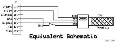
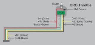
I doubt those are temp sensor wires on the throttle connector - probably ebrake. Here are a couple of threads and a couple of snaps from those threads:
Lyen 18fet to Cyclone 1000watt Instructions
Headline Motor & Cycle Analyst with limit functions


Frankly, there does not appear to be a return to the controller for either Vbatt or +5V -- so the switch cannot reasonably be switching Vbatt as it does with other controllers and cannot be switching 5V back to the controller either. The Vbatt connection appears only to be used for the fairly worthless gas gauge LEDs.
So how does this thing work? Oddly, both of the images above suggest that the throttle on/off switch actually controls the power for the throttle electronics - which apparently kills the throttle signal but does not actually power down the controller - again, kind of worthless. On the other hand, if the switch actually does interrupt Vbatt, then it makes sense that the CA-powered throttle electronics would flash the LED when the controller power went away. (?)
So - something is wrong either with those illustrations or guesses as to how this thing works.
The operative word here is 'Guesses'...
Anyhow, if the illustrations above are sort of true, it appears that some bit of throttle electronics and the LEDs are drawing power from the CA throttle +5V supply and that is what is causing the change in the CA backlight when the LED blinks.
- I assume you have the green CA-DP ThrOut breakout cable connection to the controller ThrIn when you have the throttle hooked to the CA. Measure the voltage at that connection and verify that it is actually as shown on the diagnostic OUT field at full throttle.
- Also verify that the OUT field shows the max configured throttle out voltage when you are riding at WOT and not getting full power.
If the voltage in the OUT field is correct and the measured voltage at the controller throttle connection tracks the CA OUT reading, then the CA is working correctly and there is some other controller or wiring issue in play. There is nothing more that can be done but to deliver the proper throttle voltage to the controller...
- Again - guessing at what the throttle is doing, I would recommend disconnecting it completely from the controller when it's hooked to the CA. At the least this will get the menacing-sounding Vbatt away from the CA throttle connections. If the controller won't operate, then we will be pretty certain that the wiring in the illustrations above is incorrect. At that point you are either going to need some additional information on that throttle or start figuring out what the throttle connections to the controller are really doing.
Kelly doesn't supply throttles that I'm aware of, so I'm guessing your throttle came with a kit and was probably fitted with appropriate connectors for that application. The Kellys that I have looked at have wiring for throttle micro-switches but nothing like this throttle seems to provide. If you really want to use this throttle, you may have to disassemble the throttle and figure out what's going on in there. Whatever it is, The LED indicators are not useful and disabling them would not be a loss and would get the Vbatt away from the throttle connections (water in there = Vbatt into CA throttle circuit = very bad).


