
Hayds13
1 W
Just upgrade to CA 3.1 and getting the same "settings changed" issue as Dumsterdave. I’ve submitted a bug report to Grin.
FETguy said:Rob92 said:Thanks for the tip. I just applied 12v to the LED +/- pin and no splash screen now, only some flickering of the screen.
Does this mean that below parts wont fix my CA, or is there still hope?
We need to clarify how to do this test. The LED backlight for the display is connected between LED+ and LED- and has a normal operating voltage of about 3 Volts, so if you applied 12 VDC between those pins, it would just make the LED light up, and maybe damage it. Justin's original troubleshooting suggestion is:
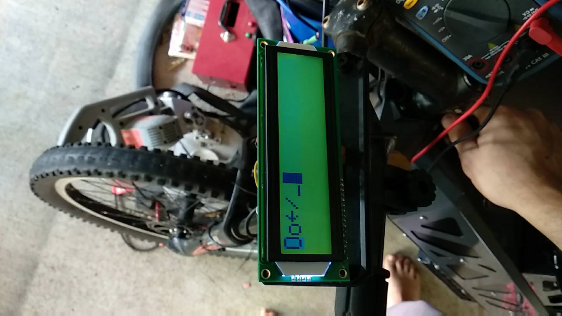
"To see if the rest of the CA is fine, just apply 12V power directly to where the output of the mosfet would normally be (or to the LED+ pin on the LCD header). If all is well it should power up to the splash screen fine..."
Note that he means that you should apply 12 VDC between LED+ and ground (black wire, or any pad on the board marked "G"). +12 VDC goes to LED+ and -12VDC goes to ground. Please try that, and let us know.
I measured Z1 and this diode is still working. Good. Let's see if the rest works.
Is it still usefull to order the items for repair? Shipping from US to EU is 18 dollars and probably takes a while I guess. Or anyone knows a good site within the EU?
You can convert the DigiKey part numbers above to manufacturer's part numbers by dropping the "CT-ND". Then you can search for them at European distributors. Hopefully you will only need the MOSFET.
Yep - We're on it.Hayds13 said:Just upgrade to CA 3.1 and getting the same "settings changed" issue as Dumsterdave. I’ve submitted a bug report to Grin.
teklektik said:Yep - We're on it.Hayds13 said:Just upgrade to CA 3.1 and getting the same "settings changed" issue as Dumsterdave. I’ve submitted a bug report to Grin.
Thanks for the bug report and post!
 I guess I can run it without the switch until I get this thing figured out. I'll get on the email now
 Dumsterdave said:teklektik said:Yep - We're on it.Hayds13 said:Just upgrade to CA 3.1 and getting the same "settings changed" issue as Dumsterdave. I’ve submitted a bug report to Grin.
Thanks for the bug report and post!
I haven't emailed grin yet, but i rode the bike today and everything seems to work until I try to enable the 3 speed switch. That is when my CA resets
madnut said:Dumsterdave said:teklektik said:Yep - We're on it.Hayds13 said:Just upgrade to CA 3.1 and getting the same "settings changed" issue as Dumsterdave. I’ve submitted a bug report to Grin.
Thanks for the bug report and post!
I haven't emailed grin yet, but i rode the bike today and everything seems to work until I try to enable the 3 speed switch. That is when my CA resets
What type of switch is it? is it grin or a generic 3 way switch. I have a generic and i had to rewire the pins and add resistors. I also have a Grin one, that works out of the box.

That's kind of ungood...Warekiwi said:IF I thumb the throttle the motor will sometimes cut back in- seemingly ignoring the speed and power settings.
This is a Temp Status screen that is unrelated to PAS torque. When you get into temperature limiting the thermometer icon appears and the third value alternates as shown below:Warekiwi said:One other query-- there is an extra data page showing on the CA3 (3.1 firmware) see photo-- what is this showing? (I don't have a torque sensor and have not activated it in the settings)

Good. It's very valuable to be able to get a CA setup file read from your CA before you cycle the power and the 'Setup Changed' message appears so we can try to reproduce this issue. So far we cannot do so.... You could also post the file here or PM me with it. Thanks for the assist!Dumsterdave said:I haven't emailed grin yet, but i rode the bike today and everything seems to work until I try to enable the 3 speed switch. That is when my CA resets
Rob92 said:Thanks for the clarification but I still get the same behaviour when applying 12v to the GND and LED+ pin. A Flickering screen. Is it worth trying to replace the parts?
I'll monitor the throttle behaviour over the next few days and try and be more detailed-- from earlier observations the throttle continued to work and ws quite controllable- it just ignored the preset limitations! Thanks for the update on the "T" page-- I couldn't find any reference to that anywhere.teklektik said:That's kind of ungood...Warekiwi said:IF I thumb the throttle the motor will sometimes cut back in- seemingly ignoring the speed and power settings.
Does the power briefly burst on then cut out or does the throttle continue to work?
Thanks. Appreciated!Warekiwi said:I'll monitor the throttle behaviour over the next few days and try and be more detailed
From the Guide:redline2097 said:What is the max power output which can be taken out from DC Jack using 20s lipos?

Partly. The speeds are a little off, but this sounds like it relates to a speedometer issue that has been addressed in the coming 3.11 release where speeds are halved above a certain speed. This would explain the release of speed limiting as the apparent speed dropped below the limit. The power thing is odd though. I can PM you an experimental in-house alpha test version of 3.11 that addresses the speed problem for you to test and report if it remedies your issue in whole or in part. If not, we will will need to pursue your report as a separate bug. This firmware is not fully vetted for beta release, but post up if you want to give it a whirl.Warekiwi said:...as the speed reached about 35mph (whilst holding throttle fully ON) suddenly the power came back on at above the preset 300W (observed at around 450W!)...
Once the speed dropped back below 25mph everything reverted to normal .
Weird??
teklektik said:I would say that you are confusing the operator throttle output voltage range with the controller input voltage range. The purpose of these CA settings is to map the BLUE range above into the RED range above. The issue appears to be the GREEN settings which you have set to reflect the operator throttle range (BLUE) instead of the controller range (RED).PRW said:When I use the throttle (you can here the sound) - power starts at about 1.50, and cuts at about 3.95, i.e. cuts out before WOT.
at Setup Throttle In, Zero throttle is 0.85, WOT is 4.28
so, I set Thrl->MinInput to 1.00, and Thrl->MaxInput to 4.13
Thrl->FaultVolt is set at 4.55
ThO->MinOut is set to 1.00, and ThrO->MaxOut is set at 4.13.
Here we want set the ThrO range very slightly larger than what the controller wants to see to operate the motor ZERO to WOT. Based on what you have written about the OUT voltages (RED), I would recommend:
ThrO->MinOut = 1.45
ThrO->MaxOut = 4.00
Here the idea is that (in PassThru mode):
- when the CA sees 'Throttle ZERO' it will send output 'Controller ZERO'
Thrl->MinInput = 1.00 ===> ThrO->MinOut = 1.45
and- when the CA sees 'Throttle WOT' it will send output 'Controller WOT'
Thrl->MaxInput = 4.13 ===> ThrO->MaxOut = 4.00
By doing this the CA re-maps the operator throttle range to the controller range to minimize throttle dead zones.
When I purchased my Mac I was told the 3 way from EM3ev was not workable with my CA3. Looking for the note...Dumsterdave said:Generic three way from em3ev. It's been working fine for the past 2 years until I've updated the firmware to 3.1
teklektik said:re-flashing fresh defaults
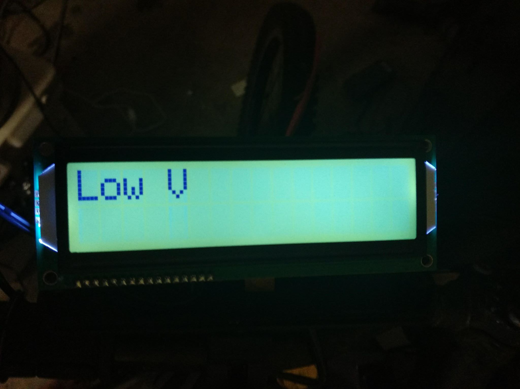
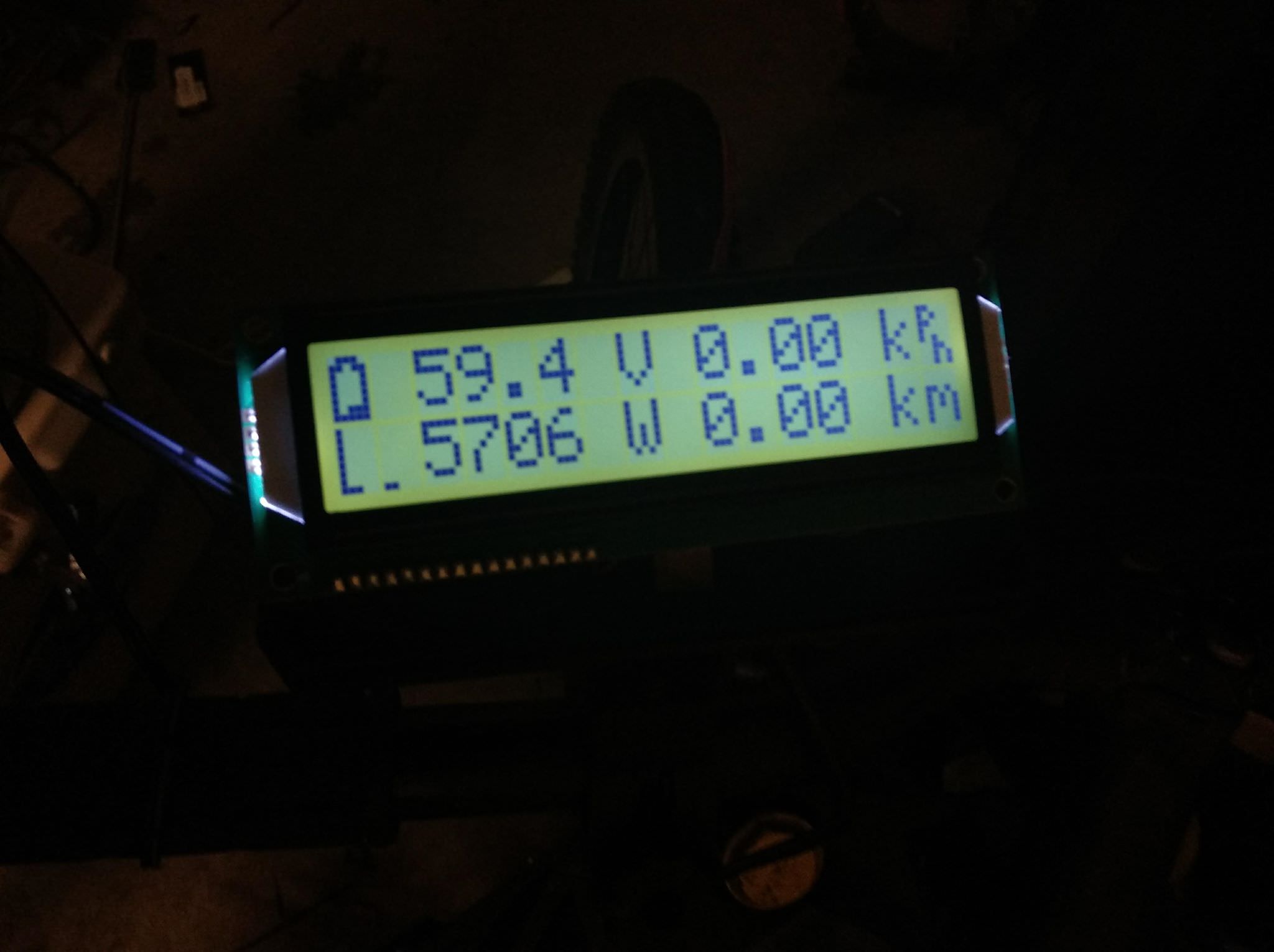
Low V with 12V is expected, when you do 12+ and grd check if any 5v of the pinouts are working.chilltrout said:The ~59.4v the screen is displaying seems like my batteries voltage (minus) 12v?
So I'm guessing something in the regulator circuit is dead, But I'm getting 150kOhm across Q1 and around 0.7v on z1 on a diode test.
I take it the 5v reg still works as the mcu is coming on so bit so Im stumped
chilltrout said:Hmm so more tests
The ~59.4v the screen is displaying seems like my batteries voltage (minus) 12v?
So I'm guessing something in the regulator circuit is dead, But I'm getting 150kOhm across Q1 and around 0.7v on z1 on a diode test.
I take it the 5v reg still works as the mcu is coming on so bit so Im stumped
