"Da bomb" cargo bike + Transmag 3kW / MAC 2kW / HS3548

The problem with doing that unfortunately is the high pole count. You can hit an electrical RPM limit pretty quick with those. They are heavy for their size as well. The only motor i would suggest for that kind of thing is what John in CR is selling.

I am having a damned hard time trying to find a suitable idler / tensioner setup.. :(
 
Nechaus take a look at this motor http://endless-sphere.com/forums/viewtopic.php?f=31&t=44058 I bought one, just got it in the mail. I agree with you that the Etek is a bit much, I am running mine on 72 volts and ended up turning my controller down to make it more ridable in the streets. This motor is only 13 lbs, brushless with sensors. I think it would be good for 10KW bursts and 3 KW continuous. Bt the way the etek on 24 volts in my electrathon is about perfect and good for up to about 30 MPH
 
Well, i have a bit of an update.
I've got the derailleurs and the brakes working on this bike now, and i hate to say it, but i LOVE riding this bike slowly on pedal power! It's a joy to ride such a bus of a bicycle! It's got sort of a cruiser-like feel with the tall BMX handlebars ( good thinking, design logic ).

I am tall and rather heavy ( 250lbs ) and find this bike to be more comfortable to ride than any other bicycle i have ridden in my entire life. That 16lbs of chromoly steel frame certainly help even out all the bumps. It seems more robust than the Yuba mundo in that aspect.

There's a bit of a problem though with designing a chain drive system. The bars that would support a motor normally are not exactly straight. Maybe i can figure out a way to even them out using washers.

I am still a little unsure how i should build some tensioners as well. Maybe some mounted bearings + shaft + a sprocket on a sorta sliding mount that i can loosen the bolts and adjust? not sure..

In the mean time, i have been thinking about mid drives a lot and how they could be much better for the hills here. I think maybe the 24FET and the motenergy motor might be better off on something else.
 
Screeeeech!
The power goals for this bike keep going down progressively :lol: know why? i now live in a place ( Utah ) that is very very very spread out, but has bike paths that go from the topmost metro area ( Ogden ) to the bottom metro area ( Provo/Orem ).

Going lower speeds has unfortunately became more desirable to stretch the battery out.

This state doesn't have hills like Colorado Springs did. it's flat unless you venture into the mountains ( i'd like to do that on a mountain bike anyway )

Fitting the dual speed reduction for the MAC has been a pain in the ass and after thinking about a mid drive system a lot, i remembered the 800W GM trike motor, in all it's 19lb ( 1.8kg ) of glory:

http://www.goldenmotor.ca/products/800-Watt-Trike-Motor.html

http://www.goldenmotor.com/hubmotors/BLT-800W Performance Curve.jpg

Or alternately i can get the 650W motor ( 6.5kg or 14lb ), but i like acceleration..

Turns out that this motor comes with a 9T 420# sprocket already installed. I've got a 41# 39T out back. I could just hook up 41# and be done.. that would give me a 4.33:1 ratio which is quite good. This would unfortunately only give me 232rpm on a 24" wheel, which is about 15mph on a 24" wheel @ 48v :lol: that oughta have some stump pulling torque.. :lol:

On 24S lipo, i could easily hit 30mph, but with an 11T on the motor, would hit something like 35mph but still have rocketlike torque, i bet. 19LBS of motor has got to put out some serious power on 92v nominal.

I am really considering ordering one now!
 
WOW, these are cheap.. $160 shipped to the USA :shock:

Gonna measure up my frame.. see if i can get pics of the inside ( crossing my fingers that this motor is kind of a low pole count, not full of bricks, etc.. :lol: ).. then prolly pull the trigger tomorrow unless someone has something objectionable to say about this motor.
 

Attachments

  • Golden Motor Canada - Express Checkout - Google Chrome_2012-11-10_22-32-48.png
    Golden Motor Canada - Express Checkout - Google Chrome_2012-11-10_22-32-48.png
    4.4 KB · Views: 1,407
This motor is looking better the more i look at it :lol: now that i've had some sleep, i've done a bit 'o math..

24S on this motor + a 4.33:1 reduction should = ~475rpm loaded on a 24" wheel. That's about 36-37mph or 58 km/hr.

I compared the specs to the golden motor HPM-5000B, and i think the 800W motor might make some good power if we feed it enough volts!!

92v on the BLT-800 spins at 2500rpm unloaded.
48v on the HPM-5000B spins at 4021rpm unloaded.

The HPM-5000B is listed to create 13nm max torque on 48v.
The BLT-800 would produce 9.6nm at 48v, but on 92v, i would guess that it produces 11-12nm on the higher voltage.

Given that the BLT-800 would be spinning at 62% the RPM, it would theoretically produce 50-60% of the torque that the HPM-5000B would, once it is geared down to wheel speed.

But here is a mystery - why does the BLT-650 make 11.3nm torque max at 48v, but the BLT-800W makes 9.6nm? maybe they didn't push it hard enough on the dyno.
The maximum efficiency point is at 6nm for the 800w motor and 4.6nm for the 650w motor, so i am thinking that they just didn't push the 800w as hard. The 800W should handle more constant power i guess?

The unloaded RPM for the 800W is 1333 versus ~1150 for the 650W and 500W motors though, so that might be the difference. Less torque, but higher speed.

http://www.goldenmotor.com/hubmotors/BLT-650W Performance Curve.jpg

http://www.goldenmotor.com/hubmotors/BLT-800W%20Performance%20Curve.jpg

So the constant loaded torque when reduced 4.33:1 for the 800W x 48v would be 39.57n-m. ( 29 ft-lb ) at 234rpm ( 80% efficiency! )
For the 650W x 48v, that would be 45.465n-m. ( 33.5 ft-lb ) at 199rpm ( 81% efficiency! )

Let's compare this to golden motor's 9C clone ( the pro-kit motor, not the magic pie ): 18.6n-m ( 13.7ft-lb ) at at 266rpm ( 77% efficiency on 36v. Woah! that's pathetic :lol: No wonder those motors make so much heat!

29 / 13.7 = 2.11 times more constant torque from the GM BLT 800W motor than their 9C clone :mrgreen: If i get extra torque constant from running 24S, maybe i get 2.25-2.5 times more torque..?

let's compare it to a Crystalyte HS ( per the dyno test on crystalyte.com ):

4:33 GM BLT-800 motor on 48V: 39.57NM constant at 234RPM - 80% efficiency
Crystalyte HS3540 on 48V: 26.53NM constant at 271RPM - 83.2% efficiency

Since the Crystalyte HS is running 14% faster, let's take 14% off the BLT-800's torque figure..

BLT-800W: 34nm constant, HS3540: 26.5nm constant.

By these numbers, the BLT should produce 33% more torque constant than the Crystalyte HS 3540.

So maybe the BLT-800 can perform more like a Crystalyte 53xx or 54xx? But the motor is 19LBS and only $108.. O_O

Phew, i am tired from all this bench racing.. :lol:
 
I've done more thinking and more calculations. Like 8 hours of serious asperger-syndrome-esque research and development :lol:

BLT-800W it is, most absolutely.
Nothing goes on a cargo bike designed to go super long distances better than a giant heavy 80%-85% efficient direct drive inrunner :mrgreen:

I've ordered a BLT-650W and a BLT-800W yesterday.
 
Allright, the BLT-800W is a bust. I have a 650W on hand and it is too damn wide, and there is no place to mount it, literally.

bltmounting.jpg


bltmounting2.jpg


The main draw with the BLT was the single 3:1 reduction to the back wheel, but this isn't going to work well on an upright bike due to the motor's size.

So i'm back to toying with the MAC motor :lol: Finally figured out a way to get the chainline straight enough on this frame, after some experimentation.

dabomb4.jpg


I wanted to mount the MAC near the chainstays but the tapered frame on this bike would mean that the BMX chain scrapes against the chainstay :(

dabomb5.jpg


Another angle of the problem..

Now if i move the chain upwards, then the chain isn't hitting the chainstay.

dabomb8.jpg


Now looking at the pictures of the bike with the gas motor ( yeah, this frame was built around the gas motor basically.. ), i figured if i replicated the staton gearbox mount, i might get a workable chainline.

dabomb6.jpg


I learned how to use an angle grinder today and made this plaete.

dabomb7.jpg


So here's how i plan on setting up the 2 stage reduction! Everything mounts up to the plate, and washers are used here and there to get a perfect straight chainline.

I just have to order some different gears, mounted bearings, and shaft now. Time to sink in another $100 :lol:

I am going for a 6.28:1 ratio on a 24" wheel, which should give me 30mph on 12S/46v with lots of torque ( on that voltage, this motor would be rated to do ~1500w continuous ). On 20S, this should produce 40mph.

Anyway i think i've figured out the hard bits; i'm close to having this properly mounted up.
 
I've figured out what i want to do with gearing.

7/8" shaft 14T #35 sprocket from usabearingsandbelts
to 3/4" shaft 35T #35 sprocket from usabearingsandbelts

That makes for a 2.5:1 ratio

+

3/4" shaft to freewheel adapter http://www.staton-inc.com/store/pro..._sprockets_1_10_wide_2_set_screws-985-50.html

3/4" 16T 1/8" wide BMX sprocket ( many manufacturers sell this )
kingsalesandservice 39T BMX sprocket ( sold as a #40 but it's really #415 )

That makes for a 2.44:1 ratio

Total reduction ratio: 6.1:1

On 12S voltage this should mean approx. 30mph.

These are wimpy ratios, so later on if i get a higher KV motor, i can possibly run 4:1 + 3.9:1 to get 15.6:1 total.
 
Allright, i ordered up all the needed bits, and the rest is a waiting game.

I cross shopped a bit before ordering and found out that:

robotmarketplace.com - while they have a nice site, their stuff gets spendy quick, but the shipping cost is low.
usabearingsandbelts.com - these guys were much cheaper for the sprockets and chain, but some items had bizarrely high shipping cost attached.
surpluscenter.com - almost everything was cheaper here, and the cost shipping is reasonable ( I am closer to them though, so that might explain things ).

I could have paid $110, $90, or $60 shipped respectively for the parts i needed.

So yeah, a double or even triple reduction setup can look really expensive - if you don't shop around.

Anyway, i plan on having a ghetto 2 speed transmission on this setup. A 12T and a 14T sprocket on the motor should allow me to switch me over from 7.1:1 to 6.1:1 - aka 25mph cruising to 30mph cruising on 12S. The way to switch the gears involves me stopping the bike and moving a few things :lol: but it should help scale the mountains out here ( very steep, and very continuous )
 
Uhmm.. anybody out there? :lol:

Anyway, I have all the reduction and motor bits i need now.. and a plan to put them all together.

reductionweight.jpg


So far, without chain and bolts, it's looking like 5lbs of stuff though :(
I can cut the keyed shaft down to about 1/4th of the size you see
I'm wondering though if i can run just 1 bearing in the jackshaft though. If i run both bearings, the jackshaft might stick out too far anyway.

I feel like i should have just ran the big motenergy at this point. But mounting it may have presented the same problem as the BLT, on this frame. I would have probably still needed a jackshaft in order to get the power in the right place.

Blag! Well, i am going to ditch the dual gear idea for the moment. I ordered a 30T sprocket to hopefully cut down on the rotating mass here. I'll run the 12T to the 30T. Hopefully the tiny 12T sprocket can hold up well enough.

tinysprocket.jpg


^--crossing my fingers that this can hold 8NM / 6FT-lbs.
 
That's one thing I ran into when I tried a reduction unit - the weight adds up quickly.

Just run one chain to a big chainring, put a fairing and tailbox on the bike and haul ass. You're not going to let Dan Hanebrink's Hustler outpace ya, are you? :lol:
 
Unfortunately what's going on here is that the 7/8 shaft really limits my sprocket and chain options. I should really be running something like a 10T #25 to a 25T #25 with a 1/2in. shaft for the first stage. This frame also prevents me from putting the motor closer to the wheel sprocket. So i need longer chain. That sucks.

It's a 16lb frame alone, so weight isn't too big of a deal. it's the rotating mass i'm worried about.

I might get crazy and drill some lightening holes in the big 30T and 35T sprockets, then cut the shaft on the motor down by about half. The 35T #35 sprocket is over 1.5LB alone. Truly excessive!
 
You know, you don't have to run the cables through the stops underneath the rack top. You can just run full housings from the front triangle stops on back, and route them however you like.
 
True;

Anyway, i have great news about the reduction build.

reductionweight2.jpg


I cut the shaft down, and it looks like if i can get away with using just one mounted bearing, the entirety of the rotating mass outside of motor and chain would be 2.3lbs, and the 35 tooth sprocket makes up 1lb of that weight. The 30 tooth sprocket i am waiting on should be lighter, and i will drill holes in it to get the weight down further as well. Maybe i will have 1.5-1.75lb of rotating mass. That's not too bad.

After playing around with motor mounting options, i figured out that i could bolt the stator straight to my reduction mount plate. In fact, that would be the easiest way to do it.

mac_plateweight.jpg


I weighed the plate that the stator bolts to, and it's 2lb of steel. All the plate does is allow for mounting with the 4 bolts on the outside. I won't be using those other 4 bolts on the outside. So take a hint on what i am thinking of next :lol:

mac_plateweight2.jpg


Yep, i am going to replicate the plate with some very thin steel! The stator should be able to use the big long motor mount as a heatsink, and i will shave just about 2lbs off a 9lb motor. :mrgreen:

dabomb7.jpg


Here is a helpful illustration that shows what i mean. The 2 bolts near the axle here are 2 of the 4 stator bolts. I can ditch the l-brackets in this pic... :]

bigmac14.jpg


bigmac_22.jpg


See the 4 stator bolts? the neo magnet ring and axle just slip over this, then the silly 0.2lb plastic case goes on to the 2lb steel plate.

7lb 1.5kW-2.0kW continuous motor = win
 
Make that bus!
...
subscribed!
 
LOL.. thanks :D
Tomorrow, i will get the last piece i need to complete this build - the 30T sprocket, which i will weight optimize tomorrow or the next day. Then get everything together..

But i am missing a 35 pitch tensioner :(.. might end up needing one.. but dang it, i can't manage to find one online or concieve of building one with the tools that i have. Any suggestions?
 
neptronix said:
But i am missing a 35 pitch tensioner :(.. might end up needing one.. but dang it, i can't manage to find one online or concieve of building one with the tools that i have. Any suggestions?
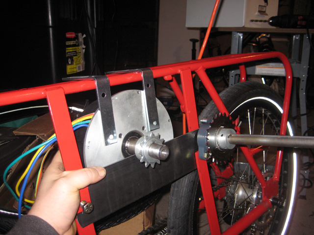
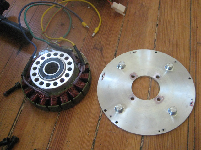
Up until the idea to lose the heavy motor backing plate, I would have said: skip the idler and tighten the reduction chain directly - slot 3 of the 4 motor mounting bolts so the motor can be rotated on one bolt (bottom bolt) and other three tightened alternator-like (center compass leg in bottom and scribe appropriate radius curves for other three).

Maybe something similar with a thin subplate for the motor cover or just get the original motor cover machined out to lighten it. Auto machine shops can do this pretty cheap and quick with just a verbal description... If you went the 'lightening' route, you could build this weekend and do the lightening later at your convenience...
 
Tele, i get what you are talking about, but i don't have a compass or a way to cut precisely ( still figuring out things i didn't learn in metal shop in high school ).

But you got me thinking, so i have to give you some credit. As soon as i read your post, i headed out to the hardware store and found something awesome called a t buckle, after checking out some other things that had a slotted bore to them ( like door hinges, lock sliders etc )

tbuckle_tensioner.jpg


These things have perfect slotted bores to them! I just have to sand the inner bore down by ~0.5mm, and the bolts for the motor will slide through and be nice and tight. they will be attached to the motor mounting plate via a L bracket, and the tension on the motor will keep them snug on the plate. I can also use a long 'set screw' on the left and right side to keep the motor in place if it wants to move.

And for the tension to the wheel, well the bike has sliding dropouts already, and i am not using the rear brake ( will be using regen ), so the alignment of the rear wheel can be adjusted about an inch ( 25mm ) on this frame! That shouldn't be a problem :mrgreen:

I think i'm set! Just waiting on the 30T gear. Tomorrow i will go blow a day in the garage and hopefully have it on the road soon.
 
something awesome called a t buckle
If you ever need a different size that's not in stock locally, they are listed under turnbuckle

A chain tensioner/idler doesn't neccessarily need teeth, you could cut a groove in a skateboard wheel. here's a chain guide/support I made a while back with an inline-skate wheel I got at a thrift-store for just a couple bucks. To cut the groove, I tightenend the wheel onto a section of all-thread rod, and spun the wheel with my cordless drill while I held a coarse file against the tread. The wheel was spinning away from me, so if it got loose it would stab the wall instead of me.

file.php


I am also very impressed by denisesewa's GNG chain tensioner for the DIY.

null-8.jpg
 
Thanks for the note about the turnbuckle.

Hey, it's true that you don't need teeth on a rolling tensioner; however, there has got to be more friction in a system like that. I have a tensioner for my extended length bike chain, and it's a plastic roller.. it makes a lot of noise and eats at my pedal power :|

If i like how this motor performs, i'll probably go with a belt for the first stage reduction. I went with chain bits because they were much more affordable. But getting friction to an absolute minimum is what i'd like to do later.

Anyhow, it's been consistently below freezing here in Utah. I thought i'd get the bike done this weekend, but braving the freezing garage has been hard to muster ( currently 26f / -3c ). Maybe i'll give it a go today.. but this build might be on hold 'till early spring :/
 
neptronix said:
Thanks for the note about the turnbuckle.
...
Anyhow, it's been consistently below freezing here in Utah. I thought i'd get the bike done this weekend, but braving the freezing garage has been hard to muster ( currently 26f / -3c ). Maybe i'll give it a go today.. but this build might be on hold 'till early spring :/

I've used both a kerosene heater and a "portable buddy" propane heater (indoor rated). Harbor Freight and Northern Tool carry both types. I find that the kerosene heater can generate a lot of heat on less than 2 gallons kerosene, but the "portable buddy" is easy and convenient to use and should run a very long time on a 20lb cylinder with adapter hose.

Two summers ago, I had to insulate both the garage ceiling and garage doors to make the garage bearable (in either winter OR summer). (I added a radiant barrier to the styrofoam garage door insulation.) After doing that, it made the garage very habitable with either heat source even in very cold nights. Nowadays I can dress warmly, like in a hoodie, and work in the garage with no heat source comfortably.


JKB
 
My garage is insulated somewhat, just full of cracks and nooks unfortunately. I've now got a little 800W heater; seems to help. I can tolerate 35-40f now with a hoodie on, not bad.

So i banged on some metal a bit more today.
Unfortunately, this frame is being a serious pain in the ass. I went to *finally* mount the jackshaft today and found that the tapered design also leads to me having about oh, 1.5mm of space between the chain and another one of the tubes.. As the bike bounces around on potholes, turns, and such, i'm sure the flex of everything will = chain eating away at the frame.

I am going to try adding 1mm inner spacers to the mix, other than that i am really stymied.

If the frame wasn't tapered at such angles, this build would have been done by summer, no question. All the weird angles and chain line issues have left me mystified as to how to mount up something else for a long time now.
Going off design-logic's webpage, it looks like they are using a 1:1 ratio to the rear wheel, at a particular angle. It's as if the frame is really designed around that staton gearbox and nothing else. No other scenario will really work.

Yuba_Mundo_V4_frame_2.jpg


Yuba_Mundo_V4_frame_3.jpg


Here is the yuba mundo, for comparison.

I'm gonna give it another go tomorrow though. We have just a few days of 40f left in the year. I don't want this MAC motor collecting dust any longer.
 
Back
Top