eTim
1 mW
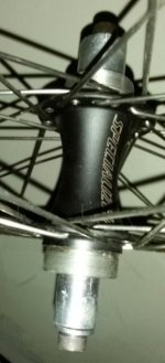
...and I've never done anything like this before, so I would love to get some feedback! About a month ago I started seriously working on my ebike project that I've had the idea for since I first got my flip flop hub bike. Basically, and I'm sure it's been done before, is to use the unused sprocket on the left side of the hub to power my bicycle. I specifically want to make everything myself, because that's the challenge and the fun of it. Let's get on to my idea for the drive.
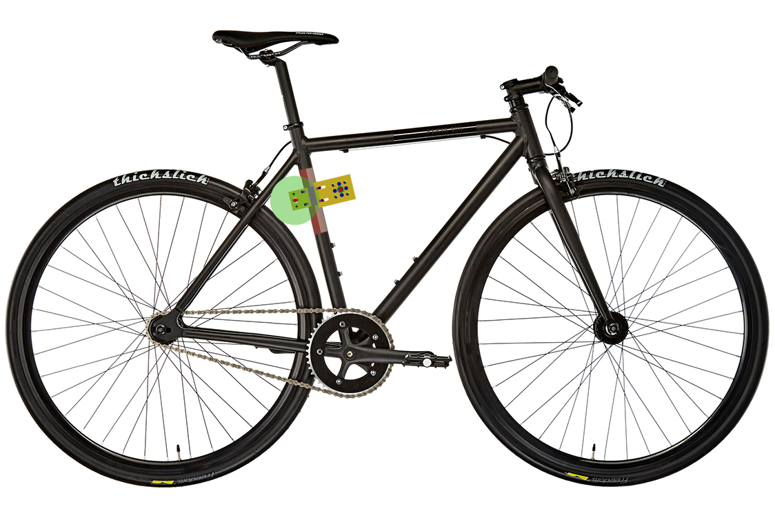
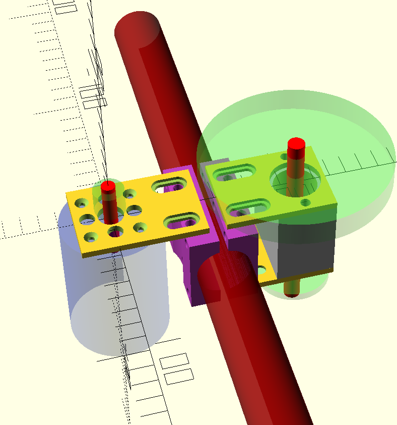
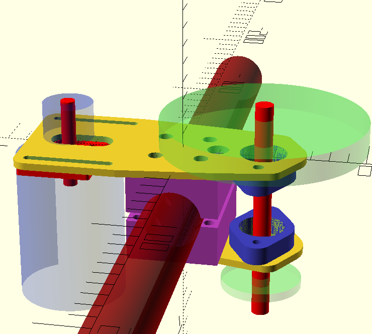
This is the current version 1.0. In the image the motor is mounted on the right and the reduction shaft is on the left, driven by a large gear wheel. (I'm sure this is not entirely to scale, but I did make the frame tube the same diameter and tried to line it up as best I can)
It would be a belt driven system from the motor to the trough shaft, and from there chain drive to the rear sprocket. Currently I'm planning on a 6:1 ratio on the belt drive and a 42 tooth rear sprocket, with easily swapped sprockets on the trough shaft :wink: So a lot like the recumpence drive, I guess, but then self made.
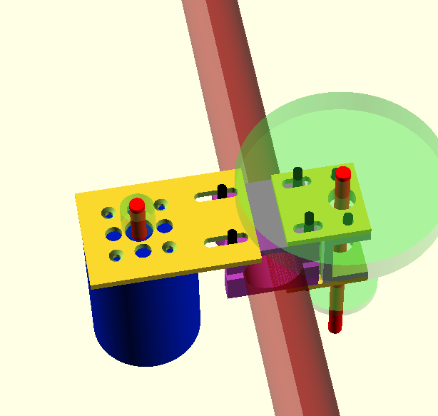
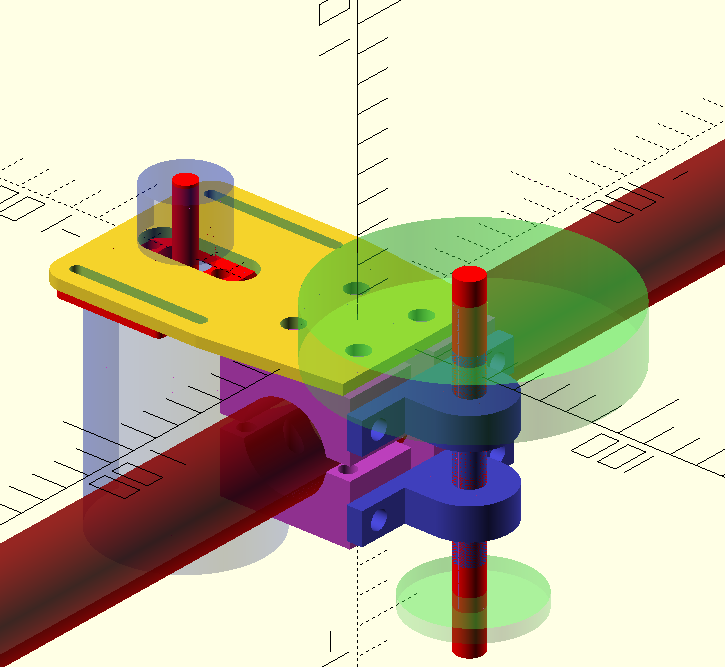
Some context: the motor is blue, it's shaft is red, the yellow plates are, well, plates, the red tube is the bycicle frame tube, the green wheels are the gear wheels, the grey U shape is the trough shaft mount, this would house bearings to hold the trough shaft of the reduction drive and finally the black tubes are temporarily there to show screw positions and how far they go into the material.
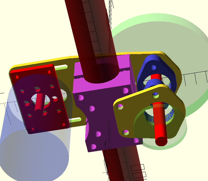
In this image here you can see the motor with it's shaft position in the mount, and the pulleys which are a bit transparent.
I tried to make multiple parts to keep cost down, the yellow plates could be laser cut, leaving only the tube mounts and trough shaft mount to be CNC'd, plus it leaves more adjustability.
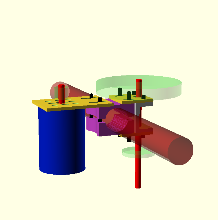
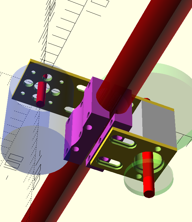
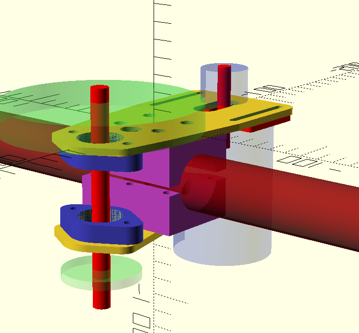
This is a more side view of the assembly. I'm not sure about the 'screw pattern'(?) I want to use. On the left side of the frame tube I want to make the top frame mount holes without thread and only the bottom pink frame tube mount have threads. On the right side of the tube I will then mount both sides of the trough shaft plates on the tube mounts, leaving only the left side of the tube mounts to 'pivot/bend' to create a pressure fit on the frame. I'm not sure about this, what do you think of this?
Another idea I'm now thinking about is to make the trough shaft mount one piece, including the tube mount, moving the 'slot' between the two frame mounts to the (in this image) top and bottom of the frame tube, and fingle something out with the motor mount. This would mean I have less adjustability on the troughshaft though. Currently I have to adjust 4 screws for a single axis of adjustment though, and I'd like to add an idler pulley to the motor drive side, and I have no idea where to put it right now.
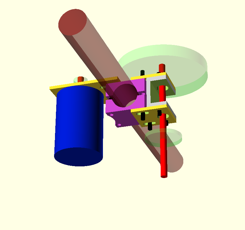
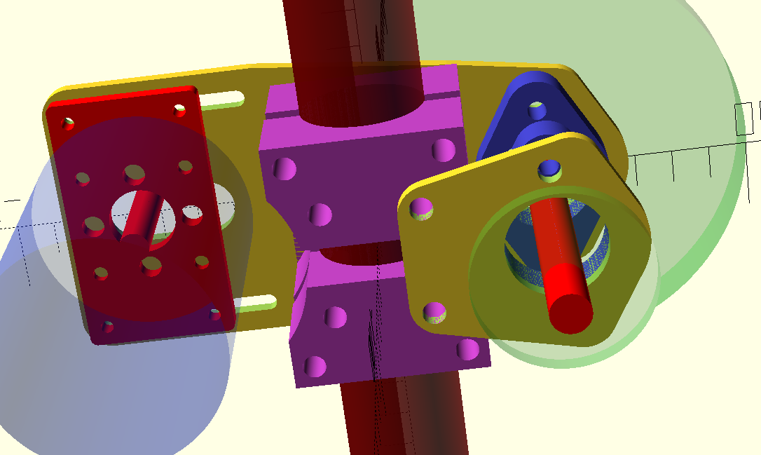
Here's another pic of the underside of the mount.
To give some context on the bike I'm going to build and how much power I'd be putting out: I have a SK3 6374 168kv motor, a self made 18650 6s5p 22.2v 14.5Ah 3c pack and I'm trying to go for range more then speed. If the tests are fine I'll build another identical battery pack and put them in series.
Let me know what you think! I prefer honesty, so if it's crap, let me know
(Tool I used is OpenSCAD, it let's you make 3D models with code it's pretty frigging awesome)

This is the current version 1.0. In the image the motor is mounted on the right and the reduction shaft is on the left, driven by a large gear wheel. (I'm sure this is not entirely to scale, but I did make the frame tube the same diameter and tried to line it up as best I can)
It would be a belt driven system from the motor to the trough shaft, and from there chain drive to the rear sprocket. Currently I'm planning on a 6:1 ratio on the belt drive and a 42 tooth rear sprocket, with easily swapped sprockets on the trough shaft :wink: So a lot like the recumpence drive, I guess, but then self made.

Some context: the motor is blue, it's shaft is red, the yellow plates are, well, plates, the red tube is the bycicle frame tube, the green wheels are the gear wheels, the grey U shape is the trough shaft mount, this would house bearings to hold the trough shaft of the reduction drive and finally the black tubes are temporarily there to show screw positions and how far they go into the material.
In this image here you can see the motor with it's shaft position in the mount, and the pulleys which are a bit transparent.
I tried to make multiple parts to keep cost down, the yellow plates could be laser cut, leaving only the tube mounts and trough shaft mount to be CNC'd, plus it leaves more adjustability.

This is a more side view of the assembly. I'm not sure about the 'screw pattern'(?) I want to use. On the left side of the frame tube I want to make the top frame mount holes without thread and only the bottom pink frame tube mount have threads. On the right side of the tube I will then mount both sides of the trough shaft plates on the tube mounts, leaving only the left side of the tube mounts to 'pivot/bend' to create a pressure fit on the frame. I'm not sure about this, what do you think of this?
Another idea I'm now thinking about is to make the trough shaft mount one piece, including the tube mount, moving the 'slot' between the two frame mounts to the (in this image) top and bottom of the frame tube, and fingle something out with the motor mount. This would mean I have less adjustability on the troughshaft though. Currently I have to adjust 4 screws for a single axis of adjustment though, and I'd like to add an idler pulley to the motor drive side, and I have no idea where to put it right now.

Here's another pic of the underside of the mount.
To give some context on the bike I'm going to build and how much power I'd be putting out: I have a SK3 6374 168kv motor, a self made 18650 6s5p 22.2v 14.5Ah 3c pack and I'm trying to go for range more then speed. If the tests are fine I'll build another identical battery pack and put them in series.
Let me know what you think! I prefer honesty, so if it's crap, let me know
(Tool I used is OpenSCAD, it let's you make 3D models with code it's pretty frigging awesome)


