spinningmagnets
100 TW
The builder speaks French
http://www.instructables.com/id/transparent-gearbox-on-a-homemade-bicycle/?ALLSTEPS
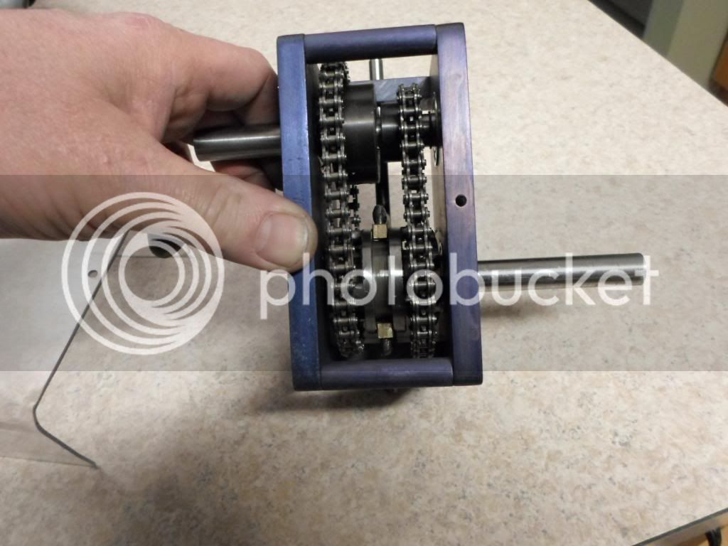
The power input, sliding single-dog, and gear selection is on the top shaft. The bottom shaft is the output, and the only reason (that I can see) for the 4th chain (the gray one) is to add more gear-up inside the housing, so that the chainring on the outside can be smaller.
All the four sprockets on the bottom shaft are fixed to that shaft.
All four sprockets on the top shaft individually sit in their own tube-adapter that allow each of them to float on the input shaft. There is a longitudinal groove in the input shaft, and a square cross-sectioned rod slides back-and-forth in the groove. On one end of this sliding shaft is the brass shifting-fork adapter, and the other end (which we can't see) has a finger sticking out, to slide into a notch on the ID of the desired gear.
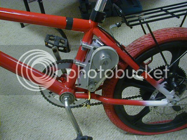
If he had extended the top shaft out both sides of the housing, and then connected the BB to the input shaft by a chain and a freewheel, he could've had an E-bike where both the motor and BB had three gears. I think this trans would've worked great with 2-gears that are widely spread, 30-MPH top speed, and 15-MPH for off-road so the motor was using high-RPMs on a slow uphill. Much better than using half-throttle and half-RPMs on a steep uphill.
The tooth-count on the lower shaft sprockets is 13T/15T/17T, The lowest gear is a 23T:13T reduction, high gear is an overdrive 13T:17T, cant see second gear.
If you don't have the tooling to make the proper groove in the drive-shaft, you could cut a slice lengthwise out of a thick-walled tube and DP-420 it onto a solid shaft.


http://www.instructables.com/id/transparent-gearbox-on-a-homemade-bicycle/?ALLSTEPS
The power input, sliding single-dog, and gear selection is on the top shaft. The bottom shaft is the output, and the only reason (that I can see) for the 4th chain (the gray one) is to add more gear-up inside the housing, so that the chainring on the outside can be smaller.
All the four sprockets on the bottom shaft are fixed to that shaft.
All four sprockets on the top shaft individually sit in their own tube-adapter that allow each of them to float on the input shaft. There is a longitudinal groove in the input shaft, and a square cross-sectioned rod slides back-and-forth in the groove. On one end of this sliding shaft is the brass shifting-fork adapter, and the other end (which we can't see) has a finger sticking out, to slide into a notch on the ID of the desired gear.
If he had extended the top shaft out both sides of the housing, and then connected the BB to the input shaft by a chain and a freewheel, he could've had an E-bike where both the motor and BB had three gears. I think this trans would've worked great with 2-gears that are widely spread, 30-MPH top speed, and 15-MPH for off-road so the motor was using high-RPMs on a slow uphill. Much better than using half-throttle and half-RPMs on a steep uphill.
The tooth-count on the lower shaft sprockets is 13T/15T/17T, The lowest gear is a 23T:13T reduction, high gear is an overdrive 13T:17T, cant see second gear.
If you don't have the tooling to make the proper groove in the drive-shaft, you could cut a slice lengthwise out of a thick-walled tube and DP-420 it onto a solid shaft.
")