DIY Pulse Arc welding copper directly to cells

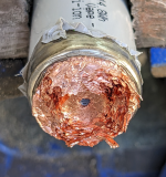
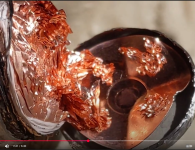
Actually having watched this video on the internals of a JP40 I don't think I need to take my test welded cells apart. There is an internal copper disk laser welded to the copper current collector. This disk is in turn laser welded to the can from the outside of the can which is what the spiral pattern is. I think so long as we are not using so much weld energy we are burning holes in the can we are good.

Unlike a tabbed cell there is obviously no plastic insulator disk to melt. As an aside it is obvious from this picture why tabless is so much better.

Thoughts?
1742298831971.png
 
Last edited:
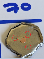
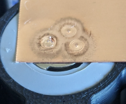
I decided to open the cells anyway, conclusion zero problems welding these at 50, or 70J or probably a lot more. Cells were discharged to zero volts then opened at the anode, outside in a breeze wearing breathing, face and hand protection. A small amount of some liquid boiled off when the cans were punctured.

Slight heat marks are visible on the inside of the can from my welds but did not transfer to the copper disk at all. I am also thinking these cells are probably fine to weld directly in the centre of the anode.
1742307487903.png1742307502634.png1742307524385.png1742307551157.png1742307574170.png
 
I can use a bit of plumbing pipe but I doubt it will work if that thick you'd probably need more power than my prototype can produce, how do you currently weld those cells?
I built my first battery using 32135 cells by soldering copper strips. Would like to build another by spot welding. Spot welding copper strip to thick copper tabs similar to the 32135 cells can be done with a welder with sufficient power, along with a special copper flux as shown in this video. That welder is around $500 though.


Pic of 22S 1P 32135 cells adding BMS wiring

IMG_4624.jpeg
 
Last edited:
That welder is cheap at $500, it has about $300 of capacitors in it. I did try welding 2mm copper with my prototype for you, not going to happen, when crank it up enough to mark the thicker copper it vaporises the thinner copper.
 
That welder is cheap at $500, it has about $300 of capacitors in it. I did try welding 2mm copper with my prototype for you, not going to happen, when crank it up enough to mark the thicker copper it vaporises the thinner copper.
Thanks for trying. Can you try welding 2 mm copper to 2 mm copper?

edit: I don't know how that copper flux works. Maybe it will help your welder to weld 2 mm copper to 2 mm copper at a lower power level. I can send you a little bit of that flux if you are curios and want to try it.
 
Last edited:
I think the only way you will do that with pulse arc is from the side so rather than trying to melt through the upper layer into the lower layer which is how the welds I've demonstrated work, you can instead fire the arc at the point where two pieces of metal meet. This needs a different type of fixturing to the weld head i've made, it is how most pulse arc welding is done for jewellery and thermocouples, etc. But in all honesty at 2mm+2mm thickness you are in the realms of a normal TIG welder anyway.
 
I am trying to weld some 0.3-0.5mm copper to those JB40’s as well. I have that large spot welder mentioned earlier in the thread along with a little micro tig welder and I have experience using the sunstone 250i micro tig system. I am looking to make a cost effective CNC welding solution for some DIY high power packs. I am really interested in giving this system a go if you are open to collaborating or decide to open source some of the design.
 
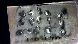
First test pack welded with 0.3mm straight copper, 12S2P AM04, was very easy and fast, took about 5mins, nothing got hot, no bad welds. I used 70J based on yesterday's investigation opening up cells. I printed a guide to make it easy to position the weld head as I didn't want to put the electrode over open air when welding the positive terminal. For a first pack using this welder I'm extremely satisfied with the result, it would have been even better if I had slightly wider copper strip (this is 30mm which is really the minimum for cells in this config).

1742376997084.png1742377025400.png
Weld guide:
1742377053718.png
 
The carbon soot cleans off with a little alcohol if you are that way inclined or want to enter your welds into a beauty contest
1742377929863.png
 
Beautiful large welds! What diameter tungsten are you using and do you find that a specific grind angle is more ideal to acheive these welds? I fired up my micro tig system last night and ran some initial test shots on 0.2mm copper to compare. It works well but if the electrode sticks after ~10 welds and gets some copper on it, it will not fire correctly until ground to a new point. I am assuming this is a timing issue with the retraction due to variable pressure and something I am trying to improve with a custom head design for my system before integrating with a CNC gantry. This is the OTS system I am working with at the moment for reference: Amazon Link
 

Attachments

  • WIN_20250318_19_53_44_Pro.jpg
    WIN_20250318_19_53_44_Pro.jpg
    357.1 KB · Views: 8
Also FWIW, I have found that using a high purity grade copper such as 110, 102 or 101 tends to significantly reduce the sooting around the welds. I suspect the lower oxygen content in the copper the better. I don't think this particularly impacts weld quality or strength, only cosmetics but I have not tested.
 
Also FWIW, I have found that using a high purity grade copper such as 110, 102 or 101 tends to significantly reduce the sooting around the welds. I suspect the lower oxygen content in the copper the better. I don't think this particularly impacts weld quality or strength, only cosmetics but I have not tested.
I've just discovered that if I clean the copper before welding it I don't get the black marks at all, so it is just minor surface contamination that is being oxidised by the arc.
 
Beautiful large welds! What diameter tungsten are you using and do you find that a specific grind angle is more ideal to acheive these welds? I fired up my micro tig system last night and ran some initial test shots on 0.2mm copper to compare. It works well but if the electrode sticks after ~10 welds and gets some copper on it, it will not fire correctly until ground to a new point. I am assuming this is a timing issue with the retraction due to variable pressure and something I am trying to improve with a custom head design for my system before integrating with a CNC gantry. This is the OTS system I am working with at the moment for reference: Amazon Link
I'm using 1.6mm tungsten, I haven't found that makes much difference (so long as you aren't blasting shards of tungsten off it by using too much current) nor does the shape of the tip. But I think this is because I have closed loop high frequency control of the entire process, i.e. it adapts to differences in the mechanics and dynamics of each weld. The welder you link to isn't capable of this type of welding, I don't want to discourage you but I think it is a non starter.

It is open loop, doesn't control (or even know) electrode position (it just fires a simple solenoid) or pressure and I think is simply based on timing. There are some videos on yt showing its internals, it is a very bad copy of a very old german micro arc welder called a Primotec Phaser mx1. My understanding from others that have had the unit in their hands is that the current former doesn't work because the Chinese cloner didn't understand how it was supposed to function.
 
Last edited:
Well, it all looks pretty great. So assuming someone would want to follow your steps, what would be the cost of building such a machine? I expect it to be much more expensive than the likes of K-weld.
 
It would definitely cost more than a k-weld, there is more electronics, plus the mechanics of the weld head and gas control. But I don't think it would be insane at least compared to commercial offerings (35k). Also depends how it is powered, I am using a cap bank I originally built for spot welding, but it works equally well from a battery, you need ~35v and it must be able to do 300A pulses (50ms).

I think comparing it to a k-weld might be like comparing the cost of a 3D printer motherboard to the cost of the whole printer with the mechanical parts. It maybe possible to put a kit together that could compete in price with the large spot welder (Glitter) that people are using for direct copper welding.

It also needs an interface to configure it, I've been using my phone as it is very quick to throw something together for prototyping but others may want a standalone unit with its own screen which would add some cost and complexity.

If I was able to gauge the level of interest and what features people would like I could work up a kit price, also what should it cost given the alternatives of a $500 Glitter spot welder or a $35000 Sunstone pulse arc system, presumably somewhere in between (towards the much lower end ;)
 
Last edited:
For the quality of welds the system is producing, even up to ~$1k in parts would be worthwhile for a prototype system. I happen to have a lot of very large ultracapacitors on hand that could be used for the pulse supply. Do you have a parts list and rough schematic you are willing to share? I would love to duplicate the setup and start testing/iterating. I can also design and layout a dedicated PCB and ther mechanical parts for the project.
 
I am curious about your precise control of that power. Are you using a high power moseft to modulate and feedback on the ADC current sense reading? Do you ignite the arc with contact + retraction or a secondary high voltage supply? For more precise retraction of the electrode are you using a servo/stepper driven lead screw actuator?
 
If you mean using a mosfet in the linear region then no this is not possible at these power levels and if you did you would need analogue feedback not via an adc. Even the best fets spec'd for linear operation can only handle ~10A in their linear region you can see this if you study the SOA curves it is a total non-starter, we need ~300A. No HF start, I think I mentioned this earlier in the thread and some reasons why it doesn't work for precise control. I don't use a lead screw it would probably be way too slow and any sort of backlash will stick the electrode, you need to accelerate the needle off of the surface to the desired arc length in a few milliseconds.
 
Last edited:
I meant operating in the saturated region of the mosfet with high frequency PWM. I remember digging into the SOA curves when working with some of the high power anti-spark circuits a few years back. Most of the open source designs utilized the linear range and were way outside of the safe operating range during the precharge phase. I have found some very high-power mosefts capable of handling the currents here given adequate cooling but I wonder if an IGBT would be more appropriate for this use case. Seems like a solenoid actuation with an adjustable hard stop would be a good option for the electrode retraction. With some clever design, the hard stop adjustment could double as the jogging mechanism too.
 
I think I mentioned earlier in the thread why PWM is problematic in this application (an arc has no inductance), if you add inductance (as per a normal TIG welder) you create a lag obviously but also danger. I'm not saying it is impossible but likely far less controllable and possibly dangerous. If you open up your Chinese Phaser clone you should get an idea of how current is controlled in these welders, albeit that implementation is apparently fully broken according to others (I haven't ever seen any other pulse arc machine other than this one i've built).
 
Last edited:
Do you have the majority of the electronics contained within the handle or is there a separate unit that it connects to? I imagine the capacitors are connected externally via the low gauge wire. It would be very interesting and impressive if you managed to squeeze the control electronics, power electronics and motion elements in the handle bit.
 
Back
Top