Hi,
After the DIY brushed ESC success, my friend and I took the challenge and designed a sensored BLDC ESC.
After reading a lot of material (thanks to ES members!) we started looking for off the shelf components to implement it.
All components where taken from Digikey.
I took on the hardware design and my friend the firmware and PC interface.
After finishing the schematics, PCB editing took around 3 weeks and the gerber files took an e-mail ride to China for fabrication.
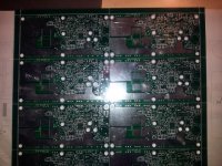
The PCB panel hosts 10 ESCs. It is a 4 layer design with 1oz copper on the outer layers and 3oz copper in the inner layers.
Most components are SMT, resistors and ceramic caps are 0805. The design is based on 12 x N-Ch MOSFETs (75V, 7.5mOhm).
3 National Semiconductor half bridge MOSFET driver will drive the MOSFET gates
A PIC18 micro will manage the ESC. This is the same MCU used in our DIY brushed ESC.
This small PIC has built in USB that we use for firmware update and parameter updates. A single PWM will drive the high side FETs using the PIC's pulse steering mode.
Pulse steering lets you use the same PWM on multiple PIC IO pins. The low side FETs will be driven at 100 duty cycle with a general purpose IO.
An external analog MUX gives the ability to use only 4 IO pins to measure 5 different parameters and even control an LED :
:
- Pack Voltage
- Motor Current
- Throttle voltage
- Switch position (mode select)
- ESC temperature
- Toggle a latched LED
Motor current is measured using the same design as in the brushed ESC. An external op amp used to amplify the current on a 1 milliOhm shunt by 20.
The op amp is also used as a second order sallen-key low pass to filter out the PWM switching. This will reduce stress on the MCU as it will have to average fewer samples.
Low pass is targeted at around 1kHz.
The hall sensors are connected to 3 interrupt on change pins.
Power to the circuit is regulated by a high voltage regulator (125V input) down to 12V for the MOSFET driver, another regulator connected to the 12V rail sources the 5V needed for the circuit's logic.
I received the PCB and components a couple of weeks ago but found the time to start assembly only today.
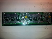
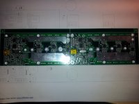
Assembly strategy - places ICs first, than SMT resistors & SMT Caps... After this I will place all the top side through hole components and than all TO-220 components on the bottom side.
I will build 2 ESCs for now so I'll have something to compare with when nasty smoke appears .
.
The firmware is written in C and uses components form the brushed ESC code (current measurement, throttle reading, temperature reading, EEPROM writing...).
We started writing the low level routines on the PIC's evaluation board, but waited for the boards to write the control state machine.
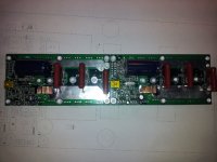
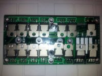
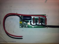
I attached some pictures of the PCB panel, IC placement & SMT resistor and caps.
That all for today... will post more as I progress.
S.B.D
After the DIY brushed ESC success, my friend and I took the challenge and designed a sensored BLDC ESC.
After reading a lot of material (thanks to ES members!) we started looking for off the shelf components to implement it.
All components where taken from Digikey.
I took on the hardware design and my friend the firmware and PC interface.
After finishing the schematics, PCB editing took around 3 weeks and the gerber files took an e-mail ride to China for fabrication.
The PCB panel hosts 10 ESCs. It is a 4 layer design with 1oz copper on the outer layers and 3oz copper in the inner layers.
Most components are SMT, resistors and ceramic caps are 0805. The design is based on 12 x N-Ch MOSFETs (75V, 7.5mOhm).
3 National Semiconductor half bridge MOSFET driver will drive the MOSFET gates
A PIC18 micro will manage the ESC. This is the same MCU used in our DIY brushed ESC.
This small PIC has built in USB that we use for firmware update and parameter updates. A single PWM will drive the high side FETs using the PIC's pulse steering mode.
Pulse steering lets you use the same PWM on multiple PIC IO pins. The low side FETs will be driven at 100 duty cycle with a general purpose IO.
An external analog MUX gives the ability to use only 4 IO pins to measure 5 different parameters and even control an LED
- Pack Voltage
- Motor Current
- Throttle voltage
- Switch position (mode select)
- ESC temperature
- Toggle a latched LED
Motor current is measured using the same design as in the brushed ESC. An external op amp used to amplify the current on a 1 milliOhm shunt by 20.
The op amp is also used as a second order sallen-key low pass to filter out the PWM switching. This will reduce stress on the MCU as it will have to average fewer samples.
Low pass is targeted at around 1kHz.
The hall sensors are connected to 3 interrupt on change pins.
Power to the circuit is regulated by a high voltage regulator (125V input) down to 12V for the MOSFET driver, another regulator connected to the 12V rail sources the 5V needed for the circuit's logic.
I received the PCB and components a couple of weeks ago but found the time to start assembly only today.
Assembly strategy - places ICs first, than SMT resistors & SMT Caps... After this I will place all the top side through hole components and than all TO-220 components on the bottom side.
I will build 2 ESCs for now so I'll have something to compare with when nasty smoke appears
The firmware is written in C and uses components form the brushed ESC code (current measurement, throttle reading, temperature reading, EEPROM writing...).
We started writing the low level routines on the PIC's evaluation board, but waited for the boards to write the control state machine.
I attached some pictures of the PCB panel, IC placement & SMT resistor and caps.
That all for today... will post more as I progress.


S.B.D


