Doc EXTREME 36 FETS controller

Doc, great respect for ur builds and achivements.

Y not just drop the capacitors donw to the pcb and throw it in a regular smaller aluminium extruded case filled with mineral oil?? Like powergrid transformers or modded pc's? The goal the less oil the less weight but surly hould conduct heat better than the air.
 
Hello

Any progress with the build?
Since this may be the only big controller out there that could handle high current its very interesting to see how it works.
You've done a great job searching those parts, it's like they where made to fit together.
One thing I really like about this build is thats its actually narrower than a 24 fet controller, that makes it alot more use able.

Pleas say you havent stopped the work :)

Ratking
 
Ratking said:
Hello

Any progress with the build?
Since this may be the only big controller out there that could handle high current its very interesting to see how it works.
You've done a great job searching those parts, it's like they where made to fit together.
One thing I really like about this build is thats its actually narrower than a 24 fet controller, that makes it alot more use able.

Pleas say you havent stopped the work :)

Ratking


Never stoped the project.. no worrie!!.. it's just on hold to leave me the time to prepare the house for the winter and some work inside my home...

I'll continu progress in few days or weeks.

Doc
 
The problem with filling the controller with oil, or potting for that matter, is that you heat up all the other components on the board. Even if you do insulate the caps, it will be a mess and probably unreliable. I think DOCs method is better.

I covered this on the podcast this week BTW :D
 
Doctorbass said:
Nice idea... BTW.. I know someone here that will provide us DUAL MOTOR CONTROLLER sooon !! :wink: with single throttle!!


About the dual controller 18 fets and dual winding.. This is a good idea... but you forget that it need 6 wired out of that motor!! :| .. and 6x AWG 10 is a bit difficult to me to cary in an X5 axel !

The 5303/06 motor is now a pure 5303 no relay.. no split... i reconverted it as OEM... 5306 just suck!.... Luke you was right about that

Doc

Why did the 5306 suck and what was Luke right about, any link to that..?

And could you share some more info on those dual motor controllers..? TIA, man. ;)
 
dangerzone said:
Doctorbass said:
Nice idea... BTW.. I know someone here that will provide us DUAL MOTOR CONTROLLER sooon !! :wink: with single throttle!!


About the dual controller 18 fets and dual winding.. This is a good idea... but you forget that it need 6 wired out of that motor!! :| .. and 6x AWG 10 is a bit difficult to me to cary in an X5 axel !

The 5303/06 motor is now a pure 5303 no relay.. no split... i reconverted it as OEM... 5306 just suck!.... Luke you was right about that

Doc

Why did the 5306 suck and what was Luke right about, any link to that..?

And could you share some more info on those dual motor controllers..? TIA, man. ;)

Follow this thread :wink:
http://endless-sphere.com/forums/viewtopic.php?f=2&t=9215&p=295337#p295337

Doc
 
Doctorbass said:

Thanks Doc, great work... ;)

One other thing, would you remember the location of the temperature sensor thread, I am planning to put some sort of sensor inside the windings of my 5305 and wonder about the best solution to prevent overheating..? I've seen your bike ride at 106km/h which is awesome, what kind of cooling did you do beside drilling those holes to keep the stator from overheating..? And did you or someone else besides Hal do some monitoring how fast do the coils commence turning excessive amps into heat in a X5 motor..?

Sorry if I ask too much but these latest results of the ES community seem great and are going in the right direction to create the ultimate bike, and sometimes I just can't keep track of the newest happenings. :)
 
dangerzone said:
Doctorbass said:

Thanks Doc, great work... ;)

One other thing, would you remember the location of the temperature sensor thread, I am planning to put some sort of sensor inside the windings of my 5305 and wonder about the best solution to prevent overheating..? I've seen your bike ride at 106km/h which is awesome, what kind of cooling did you do beside drilling those holes to keep the stator from overheating..? And did you or someone else besides Hal do some monitoring how fast do the coils commence turning excessive amps into heat in a X5 motor..?

Sorry if I ask too much but these latest results of the ES community seem great and are going in the right direction to create the ultimate bike, and sometimes I just can't keep track of the newest happenings. :)


you have to insert a barbecue sensor drilling big hole on each side of the cover
 
sjacome said:
Doc, great respect for ur builds and achivements.

Y not just drop the capacitors donw to the pcb and throw it in a regular smaller aluminium extruded case filled with mineral oil?? Like powergrid transformers or modded pc's? The goal the less oil the less weight but surly hould conduct heat better than the air.


Forget about that.. mineral oil is too complicated to avoid leak.

Doc
 
dangerzone said:
Doctorbass said:

Thanks Doc, great work... ;)

One other thing, would you remember the location of the temperature sensor thread, I am planning to put some sort of sensor inside the windings of my 5305 and wonder about the best solution to prevent overheating..? I've seen your bike ride at 106km/h which is awesome, what kind of cooling did you do beside drilling those holes to keep the stator from overheating..? And did you or someone else besides Hal do some monitoring how fast do the coils commence turning excessive amps into heat in a X5 motor..?

Sorry if I ask too much but these latest results of the ES community seem great and are going in the right direction to create the ultimate bike, and sometimes I just can't keep track of the newest happenings. :)

At 10kW in the motor ( X5) i measured a temperature increase of the stator of 22 degrees celsius from ambiant 25 degree for a 20sec full power short ride.

Important : The more hot the stator is.. the faster it heat up. itMs due to the resistance increase fo the winding function of temperature.

Doc
 
Doc,

I got the solution a cold night of riding at 4 celcius at 2 AM like we did last summer and its fix dont' need no more cooling stuff, i'm just kidding :lol:

Good day!
Black Arrow
 
BlackArrow said:
Doc,

I got the solution a cold night of riding at 4 celcius at 2 AM like we did last summer and its fix dont' need no more cooling stuff, i'm just kidding :lol:

Good day!
Black Arrow

He he, yeah, but wouldn't the controller need more 'juice' in cold temperature which would heat it up even more..? ;)

Doc, how's the 36FET controller doing when it is so cold outside..? And are there any guys who will be selling such modified 36FET 100V controllers on ES..?
 
dangerzone said:
He he, yeah, but wouldn't the controller need more 'juice' in cold temperature which would heat it up even more..? ;)

No, it's only batteries that don't like cold weather. For the motor and controller cooler is better because it means less resistance and less heat loss. Other than a tiny amount of power to run the brain of the controller, it doesn't need any juice. It's just passing the juice through, telling it where and when to go. No tubes in there that need to warm up to function. :mrgreen:
 
UPDATE 25 feb 2011. ( EDIT corrected from 25 april 2011).. No time machine invented yet :lol: Thanks andreym

I restarted the work on the 36 fets today.

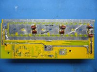
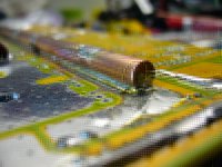
After few hours of brainstrom, i decided that i'll use two 1/4" dia cooper rod for the rail under the pcb. From one end to the other end at 100A there is only 10mV diff so the current sharing of the mosfets will be better.

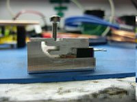
Also, instead of putting screw on the mosfet i'll use these kind of clip(spring plate) combined with screw that push on the mosfet. That will apply pressure right on the best spot. To decrease the number of plate and screw i'll use a triangle shaped plate where each of the two mosfet will receive pressure from one corner of the triangle. The third corner will be on the the heatsink. By that way each mosfet i each pair will receive the same force.

The aluminum rectangle bar where the mosfet will be pressed on will also have a groove in it to place a copper pipe of 3/16" right under the mosfet where the dye is. i'll use thermally conductive silicone to fill space between the copper pipe and the aluminum.

To let the mosfet and plate have enough room i resoldered the 0.1uF capacitor under the pcb.

Some pics:
 

Attachments

  • P1080225.JPG
    P1080225.JPG
    93.6 KB · Views: 2,636
  • P1080230.JPG
    P1080230.JPG
    70.8 KB · Views: 2,636
  • P1080233.JPG
    P1080233.JPG
    72.8 KB · Views: 2,631
Doctorbass said:
UPDATE 25 april 2011.

I restarted the work on the 36 fets today.
<snip>
The aluminum rectangle bar where the mosfet will be pressed on will also have a groove in it to place a copper pipe of 3/16" right under the mosfet where the dye is. i'll use thermally conductive silicone to fill space between the copper pipe and the aluminum.
Great news Doc!

I really like the FET clamping idea. It avoids so many of the problems with mounting via the FET tab hole.

Please don't think of this as a criticism of your design but I'm worried about the high thermal-resistance between the FETs and the aluminum bar they're being pressed against. Using a round pipe underneath the FETs results in only a few thousandths of an inch of contact between the FET and the pipe. The silicone will conduct very little heat as its resistance is perhaps a hundred times higher than that of aluminum. This results in only a very tiny active area of heat removal compared to the plate on the back of the FET. Also, the silicone might not be rated for the high heat it will experience under the FET and might flow, reducing its contact with the FET.

It's hard to beat 100% metal against metal contact over the entire rear of the FET (also using a good thermal compound, of course). This allows the aluminum bar to have the minimum thermal resistance to the FET. Acting as a heat spreader, it's easy then to transfer the heat to the pipe/silicone channel which could be just a cm. away. The heat can approach the pipe from all directions since the aluminum will spread it out, increasing heat transfer efficiency.

Just expressing a worry though. Looking forward to seeing it come to life!!
 
great scott! Thermal management, FROM THE FUTURE!

living up to the avatar :lol:

Edit: Its really nice that the high and low rails are separated on this controller. For the 18Fet version I have to electrically insulate all of the FETs which always leads to a high thermal resistance. This is setup looks like it is in a nice configuration to allow the FETs to be bolted directly to the heatsink.
 
CamLight said:
Doctorbass said:
UPDATE 25 april 2011.

I restarted the work on the 36 fets today.
<snip>
The aluminum rectangle bar where the mosfet will be pressed on will also have a groove in it to place a copper pipe of 3/16" right under the mosfet where the dye is. i'll use thermally conductive silicone to fill space between the copper pipe and the aluminum.
Great news Doc!

I really like the FET clamping idea. It avoids so many of the problems with mounting via the FET tab hole.

Please don't think of this as a criticism of your design but I'm worried about the high thermal-resistance between the FETs and the aluminum bar they're being pressed against. Using a round pipe underneath the FETs results in only a few thousandths of an inch of contact between the FET and the pipe. The silicone will conduct very little heat as its resistance is perhaps a hundred times higher than that of aluminum. This results in only a very tiny active area of heat removal compared to the plate on the back of the FET. Also, the silicone might not be rated for the high heat it will experience under the FET and might flow, reducing its contact with the FET.

It's hard to beat 100% metal against metal contact over the entire rear of the FET (also using a good thermal compound, of course). This allows the aluminum bar to have the minimum thermal resistance to the FET. Acting as a heat spreader, it's easy then to transfer the heat to the pipe/silicone channel which could be just a cm. away. The heat can approach the pipe from all directions since the aluminum will spread it out, increasing heat transfer efficiency.

Just expressing a worry though. Looking forward to seeing it come to life!!


Hey John,

Thanks for this attention in regard to my project.

Don’t worries, the plan is to put that copper pipe under the FET thru the aluminum L shape bar right under the fet… First, I thought to put only copper bar under the FET but that was way more expensive and heavy weight so using copper and aluminum combine is the key I think. Please let me know if my drawing is OK.

Thanks!

Doc
 
Ahhh, I understand now, definitely better. Thank you for that graphic!
It's often tough for a liquid cooling setup to match a good heat sink/fan combo (when looking at the entire system) but I'm excited to hear how your works out! :D
 
Bugger the heatsink compound Doc. If you really want low thermal resistance between your copper pipe and aluminium heat spreader then you need....

BzWdNgQ2kKGrHqUOKjsEOkY19fBMVrjT7gb_12.JPG


+

89490100.jpg
/
200w_cata.jpg


http://www.aws.org/wj/2004/02/046/
 
boostjuice said:
Bugger the heatsink compound Doc. If you really want low thermal resistance between your copper pipe and aluminium heat spreader then you need....

BzWdNgQ2kKGrHqUOKjsEOkY19fBMVrjT7gb_12.JPG


+

89490100.jpg
/
200w_cata.jpg


http://www.aws.org/wj/2004/02/046/

Nice find!

Where to buy thta stuff? did you already used it?

Doc
 
Yeah Doc, I've used it to join Aluminium to Aluminium which is a tad more challenging than Aluminium to Copper (pretty much any solder will easily wet clean copper).

A method I found to work was;

Clean both joining surfaces with a scouring sponge/fine sandpaper then wipe down with IPA/Ethanol. If your aluminium heat-spreader is hard anodised then you will need to work hard to get through that layer. This replaces the long term accumulated deeper oxide layer with a fresh one of minimum thickness - easier to get through later on.

Then evenly preheat the sections with a propane torch (careful of warping!, an oven would probably be better for this), then quickly lay down the required thick line/s of solder along the joint plane with a big Iron (It wont wet the Alu very well at this point, but the flow onto the copper pipe should keep the solder mobilised in a reasonably straight line). Then re-flow the line of solder with the propane torch and work your way along brushing in short linear strokes though the molten pool until you achieve decent wetting of the Aluminium. Use a small stainless steel (not brass) wire brush just behind the torches flame front. This allows the Alu-oxide layer to be abraded through whilst protected from the majority of atmospheric O2 by the molten pool of solder. It will look messy after the brushing, but you can re-flow it yet again after you've got good surface wetting, add a little more solder and you've got a smoothish fillet. I've read that Zinc based liquid flux makes things easier, but I didn't use it so I cant comment.

Both Multicore and Stannol manufacture the Pb80Sn18Ag2 combo, there may be others as well. Very few distributors stock it in small quantities though.

http://www.newark.com/multicore-solder/629443/solder-wire-alusol-0-91mm-500g/dp/15J8243?Ntt=alusol

OR;

Straightforward for me to get V V V
http://australia.rs-online.com/web/....html?method=searchProducts&searchTerm=alusol

According to the RS international homepage, Allied Electronics is the Canadian distributor V V V
http://www.rs-components.com/index.html

But a search brings up nothing, they should be able to get it though if you call them. V V V
https://www.alliedelec.com/search/searchresults.aspx?N=0&page=no_results&Ntt=alusol&i=
 
boostjuice said:
Yeah Doc, I've used it to join Aluminium to Aluminium which is a tad more challenging than Aluminium to Copper (pretty much any solder will easily wet clean copper).

A method I found to work was;

Clean both joining surfaces with a scouring sponge/fine sandpaper then wipe down with IPA/Ethanol. If your aluminium heat-spreader is hard anodised then you will need to work hard to get through that layer. This replaces the long term accumulated deeper oxide layer with a fresh one of minimum thickness - easier to get through later on.

Then evenly preheat the sections with a propane torch (careful of warping!, an oven would probably be better for this), then quickly lay down the required thick line/s of solder along the joint plane with a big Iron (It wont wet the Alu very well at this point, but the flow onto the copper pipe should keep the solder mobilised in a reasonably straight line). Then re-flow the line of solder with the propane torch and work your way along brushing in short linear strokes though the molten pool until you achieve decent wetting of the Aluminium. Use a small stainless steel (not brass) wire brush just behind the torches flame front. This allows the Alu-oxide layer to be abraded through whilst protected from the majority of atmospheric O2 by the molten pool of solder. It will look messy after the brushing, but you can re-flow it yet again after you've got good surface wetting, add a little more solder and you've got a smoothish fillet. I've read that Zinc based liquid flux makes things easier, but I didn't use it so I cant comment.

Both Multicore and Stannol manufacture the Pb80Sn18Ag2 combo, there may be others as well. Very few distributors stock it in small quantities though.

http://www.newark.com/multicore-solder/629443/solder-wire-alusol-0-91mm-500g/dp/15J8243?Ntt=alusol

OR;

Straightforward for me to get V V V
http://australia.rs-online.com/web/....html?method=searchProducts&searchTerm=alusol

According to the RS international homepage, Allied Electronics is the Canadian distributor V V V
http://www.rs-components.com/index.html

But a search brings up nothing, they should be able to get it though if you call them. V V V
https://www.alliedelec.com/search/searchresults.aspx?N=0&page=no_results&Ntt=alusol&i=

Thanks!

I wonder what is the thermal resistance of that material.. if it is higher than my aerospace grade thermally conductive silicon than i might choose the easier way with silicon.

The one i use at work are made by nusil and dow corning. It's easy to keep for me the expired date products that still work for me but wont respect the ISO norma at my work.

Doc
 
Back
Top