• Howdy! we're looking for donations to finish custom knowledgebase software for this forum. Please see our Funding drive thread

E bike controller question

mike46

1 mW
Joined
Oct 16, 2015
Messages
10
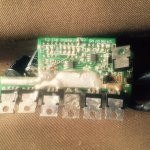
I have an older Chinese made 36 V brushed controller made by senyuan

It has 6 power transistors, a Fairchild PWM microchip and 2 large capacitors, some zenners and a diode, and a couple of small chips, look like 555s but cant tell.

One of the caps is leaking, so I will replace it. Its a 63 volt 470uF cap.

I was wondering does anyone have a general schematic on how these controllers work? What are the 2 large caps for? Can I replace the caps with a larger value, and if so, better performance?

This one does not use halls sensors

What I mean is, how the chip sends signals to the mosfets, and how that turns the motor? Does the throttle or POT somehow control voltage to the gates of the mosfets?

I could not find any spec sheet after a search. Thanks in advance for any info or help!
 
You can learn a lot about how these controllers work from this link. You can replace the capacitors with higher voltage ones and/or more capacity, which might be less liely to fail, but won't give you any more performance. They help smooth the demand from the battery. The current demand is pulsing at a high frequency. Without them, you wouldn't get enough current into the mosfets.

The operation is very simple. The battery voltage goes direct to the motor, but is blocked by the mosfets. There's 6 routes that the current can take, which the mosfets allow when open - two in each direction for the three motor coils, so each coil can push and pull each magnet round.

The controller's cpu opens and closes the mosfets in the right sequence to give correctly timed pulses of current to push and pull the magnets.

On top of the timed pulses, each pulse is broken up in to smaller chunks by PWM, which is how the power is regulated.


http://www.avdweb.nl/solar-bike/electronics/ku63-motor-controller.html

The other side of the CPU has to read the sensors (throttle, PAS, brakes, battery voltage, etc) so that it knows what power to give.

The power coming in goes directly to the mosfets and a branch is taken off to power the operation of the controller. The negative side of the power goes through a shunt. The cpu sees the voltage drop across the shunt to determine how much current flows. First it's cut down by one or more big resisistors to the 12v regulator. The 12v regulator provides the power to switch the mosfets. A branch of the 12v rail is then cut down ro 5v by a 5v regulator to power the sensors and the cpu, which use 5v logic.

This description doesn't cover all controllers, but probably more than 90% of all Chinese ones.
 
I have attached 2 pics for your reference. The bottom pic shows where 2 regular (non power) NPN or PNP transistors used to be. The board got some corrosion, so Im trying to get it back in order. Would you be able to tell from looking at this board what type (pnp or npn) those missing transistors should be? what is the purpose of these small transistors?

Also, I see allot about the throttle sending a voltage to the board. So the throttle has 3 wires, is it like a POT? The more voltage you control through the POT is how it regulates the signal to the board?

Thanks for any help
 

Attachments

  • bike controller.JPG
    bike controller.JPG
    64.1 KB · Views: 1,607
  • bike controller 2.JPG
    bike controller 2.JPG
    105.1 KB · Views: 1,607
My controllers is not the brushed type with shunts etc; it seems more simple. There is an op amp and voltage comparator (not sure of their function) the pwm chip and caps and zeeners

So you saying the voltage goes to the source to drain of the mosfets, depending which mosfet pair is on? What turns on the gate? The PWM chip? Something has to switch on the mosfets correct? I dont understand the relateionship between the throttle, PWM chip and gates of mosfets

Thanks for any help
 
As far as I can see, that's a standard brushless three phase controller as I described. It's a little old fashioned because modern ones have much more processing power and can work much faster.

Mosfets are swithed by transisters. The cpu gives the 5v that switches the transisters, which then open the 12v to swith the mosfets.

The throttle is a hall senor and two magnets. The hall has 5v and 0v supply, and the signal changes between about 1.2v and 3.8v depending on the position of the magnets. If you take the magnets away, you get 2.5v.

I wouldn't waste any time on that controller. You can get a modern replacement for about $20 that will work much better. If your one had water in it, there could be a lot of consequential damage. If the water shorted the 12v to the 5v, which is very likely, since those voltages are on adjacent legs of the transistors, the cpu will be toast.
 
Thanks for your reply. No, this one is for a brushed 600 Watt motor I have had for a long time. The water damaged occured not when it was installed on the bike but in storage.

Id like to get it functional; it was a very powerful motor. There are no halls sensors on this motor. I just need to know the tranistors to put back in; PNP or NPN

Thanks again for your help
 
So your saying the cpu is connected to the BJTs which are then connected to the gates of the Mosfets that switch the higher current to the motor?

Out of curosity, what are the op amps and voltage comparators function?

There wasnt any batter connected during the storage, as far as I remember. I think its just corrosion

Thanks again,
 
Just to clarify, the controller is as the OP mentioned for an older brushed motor. It appears that only 4 of the N channel Mosfets are used to control the current to the motor. The middle (odd one out) TO-220 chip could be a diode it appears that one of it's legs goes to motor negative.
The TO-220 chip on the top right is most likely the voltage regulator for the logic side. As for the FET on the far left, I am not sure?

Your inclinations are correct, the gate is driven by a mosfet driver which will switch at 10-20kHz. The duty cycle of the PWM will be determined by the throttle signal. I think you will be able to work out how to fix this one if you are keen to learn more about the inner workings. It would be easy enough to adapt a arduino to the logic side if you really wanted to get it going ;) otherwise as d8veh mentioned these can be bought for $20.

To work out what type of transistors were used you will need to follow the traces back to work out the polarity than you will know if it is NPN or PNP.
 
The middle one has only 2 legs Its nomen is AIRPAX, seems to be temp control of some kind.
The other mosfets have all the same numbers. 3 of the BJTs are back to back config, and it appears their bases are all connected. The bjt on top is a 5551 NPN but the remaing one in the group of 3 is a 5401 PNP, so maybe if I get the same 5401 perhaps it will match up.
 
@bunya

thanks for your very useful information. I need to study up on microcontrollers and eventually might build something. For now, will try to get this controller working. Is there a pin on the microcontroller to put the scope probe to see the PWM output?

Do Ebike controllers use the same method as VFD motor controllers? Was wondering if its difficult to build a VFD controller as well.
 
mike46 said:
@bunya

thanks for your very useful information. I need to study up on microcontrollers and eventually might build something. For now, will try to get this controller working. Is there a pin on the microcontroller to put the scope probe to see the PWM output?

Do Ebike controllers use the same method as VFD motor controllers? Was wondering if its difficult to build a VFD controller as well.

You could get the data sheet for the chip, which will show which output pins can give a PWM output. Alternatively, there must be six PWM outputs for the six mosfets. Each will go to one of six identical transistors, so they should be easy to spot.
 
"The duty cycle of the PWM will be determined by the throttle signal."

Trying to understand how this works. The throttle is not a POT or it is a POT that controls a voltage signal to a pin on the microcontroller, sort of like controlleing the pulse width of a 555 timer in astable mode?

The lenght and polarity of the pulse determines how long the coils are energized?

what does the op amp and voltage comparator do? Why do you need those componets in the circuit?

Also, why the need for such high frequency pulses to the mosfets?
 
The duty cycle of the PWM will be determined by the throttle signal

So this is basically the same as PWM with a 555? the width of the pulse determines the average voltage?
Why is the frequency so high?
 
Back
Top