Ebike shuts down with voltage error code at 500W

iampaulpease1

100 mW
Joined
Jun 30, 2024
Messages
37
Location
86326
After many posts referring me back to the battery, I've decided to do the arduous task of ripping apart the pack and figure out where I went wrong. My bms wont display cell data all of a sudden so I hope I didn't fry it. I apologize for any spelling errors. I had eye surgery today and can barely read what I'm writing. Thanks for all the help. Ill post back when I figure out what went wrong

have searched for an answer here and elsewhere but none of the answers seemed to apply so here goes the same old question hoping for a fresher answer since 2015

I have a crappy Chinese bike which I bought from Amazon. The Hall wires came straight out the axle and we're pulled so tight that a couple broke. After ripping it apart, extending the wires a painfully putting it back together, some more broke. I bought a new 1000w motor on Ali baba.

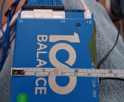
I figured while I was at it I'd build a 14s5p battery from EVE 3200mAh 18650s (10 A max draw, 5A constant) (IR on 5 cell parallel range 67m ohms to 127m ohms)with a 100balance bms and active 1A balancer with Bluetooth. and a new controller with a "900W" display (controller 40A 36v to72v). Installed the rear hub motor and new spokes. Found out my throttle was bad from error msg on display. Replaced that. Aligned brake rotors and pads Set controller up for max 20A and 48v. Set wheel size, no speed control, 42v battery cutoff, and appropriate (I think) pedal assist settings

All connections seem secure and the cells in the battery were balanced to 3.7v prior to install then the balancer rebalanced them at 4.15v (I set that as max and min at 3.1v on bms and controller) I rewired everything with 22awg wire for low voltage and 12AWG wire for high voltage. Connections twisted, soldered, heat shrink with glued heat shrink.

Now at 500w in anything over PAS2 I get a brief low voltage error code then it shuts down. I set the amp draw on controller to a max of 10A thinking max 580W (58v 10A) on a 1000w motor should be no problem. No help. All cells in p configuration are balanced to within 0.01v and at 10A draw I can't imagine it's drawing anywhere near even 1C much less the 3C they are rated at max . There is a setting asking which magnet it should base the speed at. I didn't think that was it since I set the speed limiter off. Also a setting asking "assisted magnetic steel disc type " but I tried all 3 types and no difference.

Anyone have any idea what is going on?
 
Last edited:
Could you put them together in series and parallel for an electric motorcycle? Maybe 96V and 100A. 2s3p or 3s3p. A trashed Yamaha r6 or old fz6 frame can fit a straight 4 cylinder motorcycle engine with transmission and clutch andnot cost muchif it'sbeenatrack bike witha blownup motor. That's a decent amount of space. Plus, you would already have brakes, lights, tires and wheels proportionaltothepower itcan take, and all the components that can handle extreme torque and speed. Some of the best electric motorcycles are around 14kW. Really good ones over 20kW. I'm thinking that is more about instant output rather than distance because that output at 70mph to 80mph in sport mode may only last 30 or 40 minutes and full speed at 115+mph might only last less than half that
 
If the controller failed, then it's either not mounted where/how it can shed the heat, or not designed well enough to do so, or not properly designed to limit it's current / etc to whatever it's really capable of in continuous operation.

Or it's operating beyond it's rating, which normally requires "hacking" it in some way (anything that's in it's settings, accessible to the end user, should be something it's actually capable of, so changing those settings isn't really hacking or running beyond it's ratings (ability, possibly, but if it's in the settings and allowed to be used, it's "rated" for that or else it's incorrectly designed)).

When you replace it (or repair it), pick something that can truly do what it's rated for continuously (because that's what you'll need for steep hills, etc).

If you need 50a to get up that hill, make sure the controller is able to do that "forever" and you shouldn't have problems like this one did with it.

Make sure the battery can really handle that, too (meaning the cells are able to handle it without heating up or having major voltage sag), and that the motor can also handle that (without overheating).
Ok.
 
I have built 6 packs of 14s1p cells. I'm thinking, since voltage eventually self balances in time when connected in parallel, that I can connect my bms to just one pack and connect all the packs in parallel, they will equalize in individual packs, then in series via the bms connected to the first pack. What can prevent individual cells in the 14s1p packs from getting out of whack? Do I need 6 14s1p bms's. Will the separate packs normalize voltage per cell naturally or do they normalize capacity? How can I avoid taking every single cell and connecting them in parallel while also connecting the packs in parallel? I went that route and it requires aa 50A parallel connection on both parallel and series connections. Not ideal. Any thoughts to break my brain out of this box and break the non ending loop in my head?
 
I have built 6 packs of 14s1p cells. I'm thinking, since voltage eventually self balances in time when connected in parallel, that I can connect my bms to just one pack and connect all the packs in parallel, they will equalize in individual packs, then in series via the bms connected to the first pack.

If by "connect all the packs in parallel" you mean just connect their main + and -, then no.

Doing that you only have one of them protected by the BMS--whichever one has all it's cells connected at their series interconnects to the BMS sense lines.

The BMS has no way to know what any of the other 5 packs are doing, if they are unbalanced, overcharged, overdischarged, whether they are even connected at all, or maybe even on fire. ;)

since voltage eventually self balances in time when connected in parallel,
It doesnt' balance...but every cell that is paralleled in a group will become the average voltage of all those cells in parallel, based on the resistances of the interconnects, the cells, and the voltage differences between them.

If they remain in parallel, they will "always" be the same voltage as each other.

Balancing refers to making every cell (or parallel group of cells) that is in series with other cells (groups) the same voltage as all the other seriesed cells (groups).


What can prevent individual cells in the 14s1p packs from getting out of whack? Do I need 6 14s1p bms's.

If you want them to be six separate packs, then you need six BMS for them, one for each pack.

BMS do not have "p" numbers associated with them. They do not care how many parallel cells there are, only series.

Additionally, as E-HP notes, they must be common-port BMSes (with only a C- port), to make it safe to directly parallel the BMS outputs as one single battery pack.

If you use separate-port BMSes (with separate C- and P- ports) then you must disconnect all the charge ports to discharge them, and disconnect all the discharge ports to charge them.

Otherwise teh BMS cannot protect the cells from overcharge or overdischarge, making it fairly pointless to have them installed at all.

Will the separate packs normalize voltage per cell naturally or do they normalize capacity?

Neither. The cells by themselves won't do anything at all, and without a BMS to do it for them, nothing will happen. (other than self-discharge draining each cell based on it's own internal properties, which vary unless you have matched cells).


How can I avoid taking every single cell and connecting them in parallel while also connecting the packs in parallel?
You can't, if you want one BMS.


I went that route and it requires aa 50A parallel connection on both parallel and series connections.
No, you don't.

Just don't build a pack so that all the current has to flow thru the parallel interconnects. If you do, then you do have to have parallel interconnects that can handle the full series current of the entire pack.

As has been explained before,
https://endless-sphere.com/sphere/threads/nickel-strip-ratings.98849/post-1834605
you only need parallel interconnects that handle the actual current that could flow between the cells that are not near series interconnects.

If you design the pack so that series interconnects lead from every cell in each parallel group up to the next parallel group, then there are no parallel interconnects that have to handle any significant current.

At worst they would have to deal with the balancing currents, which are on the order of a few dozen mA at most (unless you can find one of the few that does more than that--and if you need one that does more than that, you started with the wrong cells and didn't match them first, and the pack will always have problems because of the mismatched cells and their highly varied response to current draw).


If you don't have a choice due to physical layout, then you'll have to live with the problem of having to use full-pack-current-capable parallel interconnects, along with the voltage drop and wasted power and heating that you'll have within them (unless you overbuild them so much that that is negligible) .
 
It seems like the more I learn the more I realize how much I don't know.
That's how learning works, unfortunately. ;)

I started my ebike journey over a decade and a half ago***, have built several (some "from scratch") and I'm still learning....

I started my Snuggles the Wolf robotics project more than twice that long ago, haven't built one*** and I'm still learning....


***(after many more previous years of regular bikes)

****(aside from full-scale nonrobotic body prototypes to try out skeletal/joint designs, and coverings and fillings, etc)
 
Best I can recommend is before you make anything, or even design it, sit down and decide what you want it to do, under what conditions.

Decide how much money you can dedicate to it, for tools to build it, parts to make it, and spare parts to fix it for stuff that is better to get in one big batch....

Then start looking up what it will take to do what you want to do (including learning whatever you don't know about how other things that are like what you want to do have been done, and how they work, and what didn't work for various unsuccessful ones, etc).

Then start designing it.

Then go learn the things you realize you forgot to learn or didn't know you'd need to, while you're in the middle of that design process. ;)

Once it's designed, then go revise that budget to buy what it will *actually* take to make it, because your first budget will probably have been completely unrealistic. :(

Nothing is ever as simple as it seems it should be.
 
Best I can recommend is before you make anything, or even design it, sit down and decide what you want it to do, under what conditions.

Decide how much money you can dedicate to it, for tools to build it, parts to make it, and spare parts to fix it for stuff that is better to get in one big batch....

Then start looking up what it will take to do what you want to do (including learning whatever you don't know about how other things that are like what you want to do have been done, and how they work, and what didn't work for various unsuccessful ones, etc).

Then start designing it.

Then go learn the things you realize you forgot to learn or didn't know you'd need to, while you're in the middle of that design process. ;)

Once it's designed, then go revise that budget to buy what it will *actually* take to make it, because your first budget will probably have been completely unrealistic. :(

Nothing is ever as simple as it seems it sseems
 
After drawing and thinking and playing with Lincoln logs and reading more and going nearly insane, I'm pretty sure I was on the right track at the beginning. Although it's not the most energy efficient way to do it, stacking up parallel cells in a tall ++--++-- line, then connecting the long strings in series is the only way to get everything into the space I want and have the power I want without adding $200+ in (cheapest) BMS's.

So, Knowing I'm going to end up with power losses from heat, I have an idea I'd like to throw out there. If I take my 10mm nickel strip, and made a nickel/copper/nickel "sandwich " with some 4mm or 5mm (? Not sure what is available?) Copper strip, would I then have something able to carry that 50A with no problem? I can't spot weld the copper but would the welds to the nickel up and down the sides pull everything tight enough to together so I wouldn't create an even worse situation?

I'd also like to know the answer for future knowledge if this ever becomes an issue with higher amperage. I could avoid a bus bar for maybe even 75A
 
Your current battery uses 14 sticks. Each stick is your funky 5P arrangement, which is about 20mm in diameter and 320 mm long. That would mean your battery is roughly three groups of sticks in bundle, with 5 sticks in two of them, and four in the third. In terms of individual cells, it's 15 cells long and 5 cells in diameter.

If 5 cells in diameter fits down the hole. why didn't you do a conventional 5P with five cells in diameter.Then you only need 14 cells long to do the battery?

Or looking at it from different angle, use 3500 mah cells which will give you 15AH with only a 4P Will cost more, but fit better,
 
reading more and going nearly insane
You're not done until you've unlocked complete insanity. :p


Maybe I missed it, but what is the actual physical space / configuration you require the pack to fit in? If you post that or link to where you've posted it already, we can look at it with a "second set of eyes" for you and see if there is a more optimal way to lay out the pack.
Here is some of my insanity. 400mm tall x 120mm wide x 60mm deep. BMS is about 200mm long (without wires on ends) about 15mm thick and about 65mm wide
 

Attachments

  • 20250120_095736.jpg
    20250120_095736.jpg
    3.5 MB · Views: 6
  • 20250120_095645.jpg
    20250120_095645.jpg
    1.5 MB · Views: 6
  • 20250120_095701.jpg
    20250120_095701.jpg
    1.8 MB · Views: 6
Last edited:
A big block like that is easy to build as a set of paralleled blocks that are then seriesed, which is much better / easier than the other method.

You have 6p sections you want, right?

Take 12 cells, 6 with + up and 6 with - up, in the same configuration you have the cells laid out now. Connect (weld up) a single plate across all of the cell ends that are on the bottom. That is your series *and* parallel connections for that group. That group is your end group, the most negative set, and the next group up. The unconnected negative ends of the first six stick up and are on the "corner" of the battery block. (these then get their own 6-cell plate to parallel them and make your battery-negtive connection).

Do that again, and fold that between the two sets of cells, so the plate is now held between the two, with their + and - ends facing each other. This is your next two groups. Repeat this left to right right to left for the rest of the stack, as in the really crappy paint image below.
3.png

The "BMS slot" would be on one end instead of along the side, if that still works for your configuration.


Pretty sure you can even buy premade nickel plates to do this.
eidt--battery hookup sells ones that have percell fusible links NICKEL FUSE 2P-6P WIDE CONTINUOUS ROLL BY THE FOOT! 18650 CELL LEVEL FUSING
1737396579747.png
and plenty of other versions are out there too. For your purposes the ones that are solid like the above will be better than the ones that are cross-strip types like these
1737396679845.png


This thread has pics of some other types
 
Last edited:
A big block like that is easy to build as a set of paralleled blocks that are then seriesed, which is much better / easier than the other method.

You have 6p sections you want, right?

Take 12 cells, 6 with + up and 6 with - up, in the same configuration you have the cells laid out now. Connect (weld up) a single plate across all of the cell ends that are on the bottom. That is your series *and* parallel connections for that group. That group is your end group, the most negative set, and the next group up. The unconnected negative ends of the first six stick up and are on the "corner" of the battery block. (these then get their own 6-cell plate to parallel them and make your battery-negtive connection).

Do that again, and fold that between the two sets of cells, so the plate is now held between the two, with their + and - ends facing each other. This is your next two groups. Repeat this left to right right to left for the rest of the stack, as in the really crappy paint image below.
View attachment 364566

The "BMS slot" would be on one end instead of along the side, if that still works for your configuration.


Pretty sure you can even buy premade nickel plates to do this.
eidt--battery hookup sells ones that have percell fusible links NICKEL FUSE 2P-6P WIDE CONTINUOUS ROLL BY THE FOOT! 18650 CELL LEVEL FUSING
View attachment 364567
and plenty of other versions are out there too. For your purposes the ones that are solid like the above will be better than the ones that are cross-strip types like these
View attachment 364568


This thread has pics of some other types
That was my absolute first attempt before I sat down with a ruler and some extra thought, but I'd have to shave about 8mm from the interior of the hole to fit the bms. 60mm is the actual hole opening (giving me only 1mm before/in-between/after wrap and the 3 cells. I don't know how I could grind that much away evenly considering the hole is not removable from the bike and can be accessed from just one end. I did build one like that from rough measurements before I realized how critical even 2mm was in the overall scheme of things. I have considered blowing both sides and the bottom off and building whatever I wanted and THEN building the frame around it but I don't know how to weld very well and people I do know that can do it are...let's say...unreliable. The measurements I wrote are dead accurate to the mm. Any 0.Xmm is lowered to the prior mm. This is a tight fit. So much so that I'm adding 4) 80mm fans to the hole. 2 for air entry and 2 for evacuation. This entire thing is an experiment for me to learn more
 

Attachments

  • 20250120_114213.jpg
    20250120_114213.jpg
    1.3 MB · Views: 2
That was my absolute first attempt before I sat down with a ruler and some extra thought, but I'd have to shave about 8mm from the interior of the hole to fit the bms.
How about something where the BMS goes in after the battery, separately, but still wired in? Then secure it down with velcro or some other fastener so it doesn't bounce around and get disconnected or whatever.

Or a 2-part battery with a simple plug-in connector interface for a single series connection between them, with the BMS as part of the first one that goes in, and a connector for the second half's balance wires to plug into.

There are probably other schemes similar to the one I posted that would still get you minimal amounts of high current interconnects, doing as much of them as possible just like in that scheme. The simpler the interconnect and packing scheme, the easier (and usually cheaper) it is to make the connections and the less risk of problems from them, and the better the performance is.

60mm is the actual hole opening (giving me only 1mm before/in-between/after wrap and the 3 cells. I don't know how I could grind that much away evenly considering the hole is not removable from the bike and can be accessed from just one end.

Not being there to see the actual parts involved, including the space and shape and what not is much harder to come up with solutions for. Sometimes there is one that just involves thinking outside the box, or forgetting there is a box, or not realizing there is a box, all of which I have done intentially or not. ;)


I have considered blowing both sides and the bottom off and building whatever I wanted and THEN building the frame around it but I don't know how to weld very well and people I do know that can do it are...let's say...unreliable.

Welding up a frame (steel) isn't terribly hard even with a crappy cheap harborfreight wirefeed welder...but designing one that is structurally sound before welding it up and riding it can be, depending on the specific needs.

My CrazyBike2 and the SB Cruiser that followed it (we'll just leave out Delta Tripper ;) ) went thru a lot of evolution and reconstruction over the years during usage as I worked out the design kinks. They were tougher than a regular bike to do because they are for heavy cargo hauling, and not standard bicycle designs, so had to do more work and be built in ways that hadn't already had a century of trial and error behind them like regular bikes do.

But, it can be done. :)


Note being able to weld very well is something that can generally be fixed by doing it more (even just on junk metal rather than building something), and testing the results harshly, then practicing the bits that caused or allowed the failure points so that doesn't happen again.
 
How about something where the BMS goes in after the battery, separately, but still wired in? Then secure it down with velcro or some other fastener so it doesn't bounce around and get disconnected or whatever.

Or a 2-part battery with a simple plug-in connector interface for a single series connection between them, with the BMS as part of the first one that goes in, and a connector for the second half's balance wires to plug into.

There are probably other schemes similar to the one I posted that would still get you minimal amounts of high current interconnects, doing as much of them as possible just like in that scheme. The simpler the interconnect and packing scheme, the easier (and usually cheaper) it is to make the connections and the less risk of problems from them, and the better the performance is.


Not being there to see the actual parts involved, including the space and shape and what not is much harder to come up with solutions for. Sometimes there is one that just involves thinking outside the box, or forgetting there is a box, or not realizing there is a box, all of which I have done intentially or not. ;)


Welding up a frame (steel) isn't terribly hard even with a crappy cheap harborfreight wirefeed welder...but designing one that is structurally sound before welding it up and riding it can be, depending on the specific needs.

My CrazyBike2 and the SB Cruiser that followed it (we'll just leave out Delta Tripper ;) ) went thru a lot of evolution and reconstruction over the years during usage as I worked out the design kinks. They were tougher than a regular bike to do because they are for heavy cargo hauling, and not standard bicycle designs, so had to do more work and be built in ways that hadn't already had a century of trial and error behind them like regular bikes do.

But, it can be done. :)


Note being able to weld very well is something that can generally be fixed by doing it more (even just on junk metal rather than building something), and testing the results harshly, then practicing the bits that caused or allowed the failure points so that doesn't happen again.
Since my end goal is creating a road legal motorcycle built from a sport bike frame (registered) and having it outperform most others on the market (the best I've found commercially is a 24kWh 134mph bike [in sport mode] with 155 miles of range in standard mode. I'd be happy with 80% of those (most likely false) stats, I'll look at and attemp to wrap my mind around your suggestions. Run on sentence included at no additional charge.
 
That battery is going to weigh over 200lbs, almost double the weight of an R6 engine, if you build it with 18650 cells, and there’ll be ~2000+ cells, or 1100 21700 cells. I’d double and triple check each of the 4000+ spot welds so that one bad weld doesn’t ruin a pack with $7k+ of cells.
 
Back
Top