
HAL9000v2.0
10 kW
Is it possible to use solid state relays with tyristor output? I have one for three faze and up to 150A and it is 19x45x68mm. Two of them will fit in x5.
Looks like this one:

Looks like this one:
")
Doctorbass said:<snip>
These relay are so small than they could fin inside a normal X5 motor i guess ! but this is not necessary if you have no enough room inside your motor.. puting them close enough to the exterior of the motor is ok.
<snip>
potatonet said:this thread is the reason this was patented 4 years ago:
http://www.freepatentsonline.com/6967417.html


Doctorbass said:EVERY brushless motor that end with 3 phase wires can be mooded in DELTA STAR mode
To mod yours
You need:
-a brushless motor with 3 phase wire(usually they all have 3 phase in ebike and RC)
-you need one 3PDT relay or contactor(or 3 x SPDP that are activated at the exact same time by wiring their coil together)
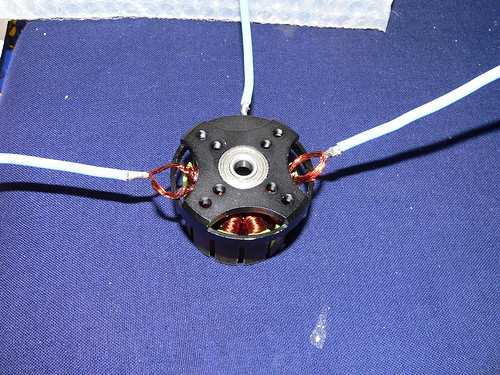
-a bit of your time to mod your actual motor by opening it and taking the 3 phase wires that are soldered ogether inside the motor(coming from the winding) and to seperate them.
-Installing one wire to every of these 3 seperated tab from the winding to finally acheive 2 wires per phase.
see the image i took here for you:
steveo said:Doctorbass said:EVERY brushless motor that end with 3 phase wires can be mooded in DELTA STAR mode
To mod yours
You need:
-a brushless motor with 3 phase wire(usually they all have 3 phase in ebike and RC)
-you need one 3PDT relay or contactor(or 3 x SPDP that are activated at the exact same time by wiring their coil together)
-a bit of your time to mod your actual motor by opening it and taking the 3 phase wires that are soldered ogether inside the motor(coming from the winding) and to seperate them.
-Installing one wire to every of these 3 seperated tab from the winding to finally acheive 2 wires per phase.
see the image i took here for you:
OMG I COULD MOD MY X5 @ 133v HOLY $%$#@
-steveo
GGoodrum said:Actually, I think most RC motors normally come with wye connections. Steve Neu, for instance, only used delta-wired motors to get kVs that were in between the standard wye winds.
-- Gary