ELECTRIC TRANSMISSION DELTA /WYE and SERIE/PAPALLEL stator

karma said:
sweet i have a working fully automatic setup thats working in initial tests. im uploading a vid. its a crude setup but it works. :)

im also up to 36amps with no problems.

http://www.youtube.com/watch?v=4xaoMLTlgyw
That is amazingly cool! So you have it working exactly how? as it reaches a certain RPM it switches, or when you open up the throttle all the way?

Edit: and also, would you mind posting some detailed pictures of your relay setup? I am still a little bit confused on how exactly to hook them up.

Thanks
 
karma said:
sweet i have a working fully automatic setup thats working in initial tests. im uploading a vid. its a crude setup but it works. :)
im also up to 36amps with no problems.
http://www.youtube.com/watch?v=4xaoMLTlgyw


Yea..... you are pretty much a bad-ass. :wink:

Nice hack!

I just thought of a plug and play variation of this:
The CA has a Speed limiter.
We could use the CA throttle control (aka ebrake, I dont use mine) and control the relays with that active low output.
You could set the transmission to change gears at whatever speed you like on the go with no additional hardware. :idea:

-methods
 
Hrmm.....

We could also change gears based on Load.
You could set the CA current limit to the desired shift point
If you draw more current than the threshold, it will switch gears.
For this setup the motor would default to high rpm and "downshift" to high torque.
This could serve to protect the motor as well.

-methods
 
get keywin to have them program it into the controller, and let the controller decide when to switch and it could shut down the drivers for the required moment to shift the latching relay. could be totally fluid too.
 
here is the pdf for the ic.

http://www.datasheetcatalog.org/datasheet/on_semiconductor/CS289-D.PDF

i have the relay working in reverse. it floats at 12v. with rpm's the voltage drops setting off the delta. im just working on adding a pot for ajustments :)

i will post pics when its in a case together.

cheers
 
More details please karma!

This looks great!

And @ methods
On the CA if you set the speed limit does it just send a hot or ground down the ebrake signal on the CA 6 wire plug?
I thought it modulated the throttle signal.. how would one wire that?
 
caleb7777 said:
And @ methods
On the CA if you set the speed limit does it just send a hot or ground down the ebrake signal on the CA 6 wire plug?
I thought it modulated the throttle signal.. how would one wire that?

The CA has an algorithm for modulating the speed. There are several well defined variables you can change to tune the response.
If you were to just hook up to the ebrake/speed control line you would find that it would float until you hit your speed limit then it would drop to ground very quickly.
The CA will try to modulate the throttle by applying a lower and lower voltage to its ebrake output but since the bike wont slow down due to this, it will drop all the way to ground.
Same effect as LVC.

There could be a small delay due to the damping of the algorithm.
By changing the variables you could make the switch instantaneous.
It sounds complicated but it is trivial. If someone wants to try it I can suggest settings that will work.

In a nutshell the CA works by "Yanking down" your throttle voltage by supplying a "stiff ground" through a diode.
So what you have is a black box that will behave like an open circuit below your set point and act like a ground above your set point.
In principal you would tie 12V to the coil of your relay(s) and tie the other end of the coil to the ebrake of the CA.
In reality this would probably be too much current for the CA so it would be wise to just have the CA control a small 5V reed-relay that in turn drives the coils of the main relay.

If this does not make sense (to whoever is reading this) then dont try it. :p

-methods
 
I got the relays I ordered, not super small but would work good for this if you aren't pulling super amounts of amps
I got them here: http://www.bestronusa.com/detail/index.cfm?nPID=4426
Fast shipping.

Less than 10 bucks each plus shipping so you have to buy a couple as it doesn't meet their minimum 10$ order but that's cool.
Two of these in parallel would provide a lot of current and gives you a 48v relay if in series

The wire inside could also easily be changed for heavier gauge if you want, appears to be 16 or 14 gauge, the plastic outside case pops right off, as you can see.
The contact set is rigid and the gap at the points is about 2 mm so all phases would disconnect and connect at damn near same time I assume

The white base plate is quite hard should handle heat fine.
 

Attachments

  • DSC00053.JPG
    DSC00053.JPG
    20.6 KB · Views: 4,679
  • DSC00054.JPG
    DSC00054.JPG
    19.6 KB · Views: 4,676
  • DSC00055.JPG
    DSC00055.JPG
    25.8 KB · Views: 4,681
  • DSC00056.JPG
    DSC00056.JPG
    25.7 KB · Views: 4,675
  • DSC00057.JPG
    DSC00057.JPG
    25.6 KB · Views: 4,677
Thanks methods.

So are you saying that the #6 Throttle over-ride (green) could be disconnected from controller completely and used purely for delta switch. It goes to ground when activated. This would be great and very simple, and add an inline switch also if you want to ride normal.

This means that the green is not a necessary hook up for cycle analyst, purely for throttle over-ride?

Does anyone know how much power this circuit could sustain? would it be okay to open the two relays above if they are in series at 48v?
 

Attachments

  • Pinout.jpg
    Pinout.jpg
    10.4 KB · Views: 4,922
the CA may not be able to handle the current needed to switch the 5V relay. however you could use a solid state relay for the coil current and switch that relay with the CA supply perhaps or have the CA drive a darlington for the coil current.

for the 24V relay to operate under a 48V pack, you can drop some of the voltage through a power resistor inline, but i suspect that relay would operate up to 32V and if it has about 30 mA current, then an 830 ohm resistor should work to drop 25V off.

or you could just switch the coil current manually.
 
That signal is an output from the CA so the CA does not need that signal hooked to the controller.
You will obviously loose your LVC, over current, and over speed control.

I sent Justin an email asking exactly how much current the throttle override line can sink.
I am guessing it will be more than enough to drive a small reed relay.
I told him what we are up to and asked for suggestions.

Just make sure the 5V relay draws little current on the coil, can transfer enough current on the contacts to drive the big relays, and can handle the mechanical shock of the system.
Also make sure it is NO and not NC (though we could make that work too)

-methods
 
Here is a 5V reed relay rated to switch half an amp.

http://www.allelectronics.com/make-a-store/item/RLY-515/5V-REED-RELAY/1.html
(Not suggesting this one, just pointing out an example)

500ohm coil
5V/500ohm = 10mA

No way would Justin design the CA in such a way that it cant sink 10mA.
I bet he totally over engineered it to sink at least 100mA

-methods

EDIT:

dnmun said:
you could use a solid state relay for the coil current and switch that relay with the CA supply perhaps or have the CA drive a darlington for the coil current.

Quite true. I suggested a reed relay to keep it simple and avoid issues of biasing etc. Everybody knows how to hook up a relay :p
Perhaps you could suggest a good solid state switch to use and the circuit to hook it up :D
 
i grabbed 2 of these

Technical/Catalog Information SD1A05A
Vendor US Relays and Technology, Inc.
Category Relays
Relay Type Reed
Mounting Type Through Hole
Termination Style PC Pin
Circuit SPST-NO (1 Form A)
Contact Rating @ Voltage 0.5A @ 200VDC
Coil Voltage 5VDC
Control Off Voltage (Min) 0.5 VDC
Control On Voltage (Max) 3.8 VDC
Coil Current 10mA
Coil Type Standard
Lead Free Status Lead Free
RoHS Status RoHS Compliant

from ebay for a 1$ each ad 3$ shipping
me happy...
 

Attachments

  • alephreedrelay.jpg
    alephreedrelay.jpg
    7.8 KB · Views: 4,979
got it, you will use the reed relay to switch the other 2 relays? from 5V.

ps: don't goober the hinge on your relay, they are ok like that and the silicon could keep it from snapping too.
 
Thanks for the heads up

There is so much excellent knowledge on this board
Thanks to all!

I found the specs for the relays i found (attached)

it shows 230 ohm on the coil. So if I added a 230 ohm resistor I could run the 24v relay right off my 48 volt pack yes?

I know this is a stupid question, but hey its been years since I took physics...... :wink:
 

Attachments

  • JQX-38F(3P 40A).pdf
    82.5 KB · Views: 122
That is correct.
Just measure the resistance of the coil with your ohm meter and apply ohms law.

If the coil calls out 24V and you have 48V then adding a resistor in series of the same resistance will put you where you want to be.
Dont forget to account for the voltage swing of your pack.
You could error on the side of efficiency or on the side of reliability.


USING THE CA
Justin got back to me.
He made a couple good suggestions:

First off, we we will need to pop the back off the CA (which I have done many times, it is easy) and solder a short across R6. R6 is a current limiting resistor in series with the OpAmp that drives the Throttle Override. Shorting this resistor will allow you to sink 10mA no problem so the 5V relay solution will work. If you use a little piece of wire you can always go back and undo this change. No biggie. Remember that the board is conformal coated so you will need to scrape away a little 1mm patch to solder in.

Justin made another good point: He suggested using an opto-Isolator for the task instead of a relay. If someone wants to do the research, this could be a good solution. The input would probably have to be biased with a single resistor and attention would have to be paid to the output side current handling. This solution would not require shorting R6 if the bias current for the opto was low enough.

The final issue (which I had not considered) is the source of the 5V for the relay. If you draw that 5V from the CA you must proceed with caution. The Linear regulator in the CA is already sourcing 7mA for the CA. Adding another 10mA draw to that will cause the regulator to burn off almost 1W with a 72V pack. This is getting close to the limit for a surface mount part. With a lower voltage pack (say 36V or 48V) it probably is not an issue.

There are probably 30 ways to skin this cat. I am sure someone will pop up here any minute and be like : "BAP BAP CHAP CHAP CHAP" and come up with an elegant solution that addresses all these issues with a 5 cent part and 3 minutes of work. :roll:

-methods

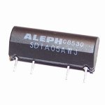
Edit: If someone wants to try the 5V relay and is running high voltage, you can probably cheese the relay coil with a small inline resistance. The turn on voltage of the relay posted above was 3.8V, so the math is simple to figure out what resistance you would put in line to lower the current. I bet that relay will work fine at 7mA or maybe even less. Just play with it and see. I figure anybody who is fooling with this Delta Wye switching is a handy tinkerer so you know what to do :mrgreen:

EDIT 2: YEA, DUH! Just grab the 5+V off the controller then we dont have to worry about the current draw on the CA regulator. duh :)
 
Sounds like I might need to design another circuit. :wink:

I think shifting based on speed will work better than based on current. That way you will start out in wye and shift to delta when the motor gets close to topping out in speed. I suppose if you were using a microprocessor to run everything you could also watch current to shift back to wye if the current got too high. This would be like a downshift when you hit a hill or something. Watching the speed could do the same thing for you I suppose.

I think it would be real good to figure out a way to breifly kill the throttle while it's shifting to keep the contacts from frying.

karma, what kind of motor and controller were you using in your test video?
 
wow... this board is growing so much! :shock: .. i've been absent for a while but i should contribute again with the next test on the 5305... or 5303 at 100V :twisted:

Doc
 
This is the R6 we are speaking of inside the CA?

solder wire across R6 to get more power out of the throttle over ride line from CA for a beefier ground rated at 10mA

I plan on using the 500 ohm reed relay with a 700ohm resistor so that I can grab a nearby 12v positive

I want to have a switch box at the front of the bike to control various things, inside will be a small 12v dc-dc converter. The CA will feed here so I can put reed relay and all inside.
haven't decided where i want the Phase relays for delta switch yet.
 

Attachments

  • ca inside mod.jpg
    ca inside mod.jpg
    85 KB · Views: 2,563
caleb7777 said:
More details please karma!

This looks great!

And @ methods
On the CA if you set the speed limit does it just send a hot or ground down the ebrake signal on the CA 6 wire plug?
I thought it modulated the throttle signal.. how would one wire that?


sorry no updates yet, im in the middle of packing to move. but i did upgrade my relayes to 40amps a phase works even faster :twisted:

im upload a vid now.

cheers
 
caleb7777 said:
This is the R6 we are speaking of inside the CA?

R6 is what Justin called out.
To be sure you could measure for continuity between either side of the resistor and the Throttle Over-ride line.

I am really glad you are grabbing this and going for it. :mrgreen:
I think using the CA will be the way to go until somebody puts together a proper circuit.

Lets see: With the CA you could:

* Shift up at a certain speed
* Downshift at a certain current
* Run one winding for the first half of your battery pack and another for the second half to maintain top speed.

Voltage, current, or speed.
(just not all three at once :mrgreen: )

Alright Fechter..... Get to work :!:

-methods
 
Back
Top