jateureka
10 kW
Subscribed for future reference, as I've just blown up my ZEV charger... looks similar to the 1200W Ecity.
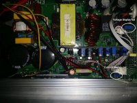
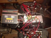
Pics of my charger in this thread http://endless-sphere.com/forums/viewtopic.php?f=10&t=52818
Pics of my charger in this thread http://endless-sphere.com/forums/viewtopic.php?f=10&t=52818