Miles said:
Lebowski said:
So to judge different configurations you need to compare the squared increase in
airgap radius (N^2) with the linear decrease in copper area (M)
Thanks Leb,
I thought about this yesterday and wrote:
"Also, although torque and current are proportionate, losses go up by the square, so that creating the same torque, by using more force, with proportionately more copper, at a proportionately lesser mechanical advantage, will be less efficient. Isn't that right?"
But I wasn't sure, so I deleted it....
")
good question,
i spose no simple statement like more copper and less leverage gives higher efficiency or vice versa can be known to be true without knowing the exact proportions of each to begin with as well as a torque level that we are judging the efficiency at etc etc.
then theres optimizing the finer points of the new configuration, like say the really long teeth (with a huge wad of copper on it that can clearly generate more flux) would surely need to also be a thicker tooth to be able to carry this now much higher flux level that on top of that also needs to travel a greater distance, this thickening would keep all of that back in balance but now has higher rpm losses from eddy currents..
and the same goes lots of little details like that, and then all the other variables that might now want adjusting to 'fit better' with the new config and some of those next changes might have been beneficial anyway and others allready pushed further in the wrong direction.
in the end there has to be a point at which a further change in either direction is taken too far and gives higher losses, so have a look at the two extremes to see where its problems may lie.
more copper has the general habit of lowering ir losses and giving the motor a higher continuous torque output, and more flux radius (as well as greater leverage) has a higher peak saturation, so more ability for burst power.
what i mean is, i dunno..
but yes, its fair to say joby would have gotten it right, so thats got to be a good direction to head.
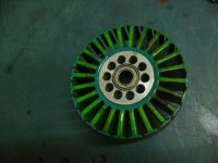
and that green stator pic is a ca120 (106mm stator od and 30mm thick) and with the very different layouts between this the 1.8kg joby jm1s its an interesting
comparison, i have good info on both, will post up.