Even Newer 4 to 24-cell Battery Management System (BMS)

Hi to everyone. I think I have the solution for the fans problem I had read before. Just source them with another regulator apart of the 12v of the control circuit. But this must be a Buck regulator Without the inductor, The motor act as inductor.... I'd attached the datasheet of the IC. Figure 27 on the 14 page.

I also have another question. I want to charge a 4S battery but if the control circuit of your design work on 12V When the charge begins. the cells have 2v * 4 = 8V in the battery pack. I don't know if can have a problem with that... have you proved the circuit with 4S?

Thanks for your collaboration.
 

Attachments

  • MC33167TG 1,75 Euro.PDF
    262.7 KB · Views: 68
That switching regulator has a maximum input of 40v. I'm looking for something that can take over 100v. Also, most brushless fan motors have a capacitor on the input so can't be used as inductors.

As for a 4s pack, you are right that the control circuit is really designed for 12v and there could be issues at lower voltages. Certainly the first regulator stage would not be needed, and you'd probably want to use a low dropout version of the 12v regulator. It may also be necessary to use 'logic level gate' FETs to make sure they are fully on during bulk charge, though I think a 4110 would be OK with 8v on the gate (it will rise quickly during charge). If someone really wants a 4s solution, I think it would need to be customized a bit for that, but is certainly possible.
 
since you are trying to power just a fan wouldnt a series of resistors work to limit the current to a safe level for the fan.

i have seen inside of some tool battery chargers like the dewalt 18 volt nicd chargers for the older drills there is no transformer (yes there may still be an emi filter coil but no mains transformer) instead it uses a series of power resistors and diodes to limit the current to the point that with a load it emulates voltage reduction.

some cheap plugin flash lights and some of the first nicd consumer battery chargers from the 80's did the same thing too.

a resistor to limit the current to a few ma and then possibly a resistor across the output to ground to hold the voltage down to prevent blowing on initial power up.

then a diode to make dc and capacitor to filter or smooth out the dc.


fechter said:
That switching regulator has a maximum input of 40v. I'm looking for something that can take over 100v. Also, most brushless fan motors have a capacitor on the input so can't be used as inductors.

As for a 4s pack, you are right that the control circuit is really designed for 12v and there could be issues at lower voltages. Certainly the first regulator stage would not be needed, and you'd probably want to use a low dropout version of the 12v regulator. It may also be necessary to use 'logic level gate' FETs to make sure they are fully on during bulk charge, though I think a 4110 would be OK with 8v on the gate (it will rise quickly during charge). If someone really wants a 4s solution, I think it would need to be customized a bit for that, but is certainly possible.
 
Yes, just a resistor works OK other than it needs to be a big one and it throws off a lot of heat.
That's exactly what we are doing for now.

Gary and I were both lamenting about how crowded our work benches are. I've been so focused on developing the circuits that I never seem to have time to clean up! Here's what mine looks like right now:
 
'

Is that some sort of purple sex toy there? Is that how you are testing discharge rates??? 8)

GGoodrum said:
file.php
 
fechter said:
Yes, just a resistor works OK other than it needs to be a big one and it throws off a lot of heat.
That's exactly what we are doing for now.

Another option is to use higher voltage fans (24V) and string them in series.
So long as they will operate from LVC to HVC you can avoid the power resistor.
(for semi-fixed cell count)

Of course if one goes out they all go out - but then the same argument is true for only one fan.

It is harder to find the smaller fans like you guys are using in 24V though - and if you run 12V fans it takes too many in series to reach 100V
I found some really nice (and thin) 40mmx40mm x 10mm 24V 70mA fans for $2 on Ebay.

They have enough CFM that two of them can manage 125W of shunt power keeping the resistors under 120C and the case under 30C.

-methods
 
Yes, if the energy wasted in the resistors can be saved, will be better. An for the idea before about the Switch mode IC... I think that can be increased voltage range with a simple charge pump. I'll put the general Idea... but I don't know about the capacitor effect of brushless motors.... If is it the only disavantage... it isn't a problem so that any inductor always has a little capacitor effect.

Anyway You are the experts... what do you think about?
 
Running fans in series to reduce the drop in the resistor is what we did on the first ones. It's not too bad if you mount the resistor right up next to the fan.

A switching power supply would be much nicer and the control circuit needs a 12v supply anyway, so if it could do both it would be good. I haven't given up on the off-line switcher chips yet.

At the rate testing is going, I don't even want to guess at board dimensions. We need to make it work right first.
 
Gary,

Suddenly I am more than happy to post my home and office work areas - they are close, but you have me beat by about 2" of pile up on the test and assembly benches (and people wonder why I don't do build videos?).

So how are we coming with these BMS? I am anxious to get one if not 2 and get moving with this (as we all are!)

-Mike
 
Right now, the v4 boards are 2.95" x 3.50".

We are still chasing down a couple things, one is that there is a bit too much voltage drop in the traces for the 1st and last channels, causing these cells to end up consistently a bit higher than the rest. Not too much, maybe 10-20mV, but enough that it is bugging me. The other thing is we are still seeing a bit of noise, that isn't really hurting anything, but it does cause the LEDs to flicker a bit, once the throttling starts. It's more of an annoyance. We're this close that I really want to fix these first.

-- Gary
 
if the noise is not hurting anything it is possible then to use a capacitor across the led to prevent the flickering.

GGoodrum said:
Right now, the v4 boards are 2.95" x 3.50".

The other thing is we are still seeing a bit of noise, that isn't really hurting anything, but it does cause the LEDs to flicker a bit, once the throttling starts. It's more of an annoyance.

-- Gary
 
Fetcher: With the Schematic I had put... The voltage in the gate of the P-mosfet will be in between Vcc and (Vcc-12) Only is needed to put a correct PWM that I think that can be any Voltage mode Switch IC, Utilizing Only the Oscilator and the Voltage comparator.... I would like to be more precise but... My only electronic equipament consist in an oxidated soldering Iron... so I can't help very much in the practice area.. so, I'm sorry.

About the current sensing that you are trying to do... Perhaps with a RC low pass filter Will be easier to the OP amp to control it.

I hope to be useful... Bye
 
Yep, that's what I'm looking at doing.
It seems that noise originating in the resistors and front end LM431 are being amplified by the transistors following and result in a very large 'white noise' content on the output of the opto couplers that messes with the throttling action.
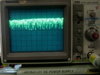
Here's what the signal on the opto output looks like at the turn-on threshold:
Scope shot opto bus2.jpg
That is not a zoomed in portion of the signal, it goes from ground to Vcc.

With some filtering in the cell circuit, I can get rid of most of it and it starts looking more like I would expect with some correlation to the PWM switching frequency (around 20kHz):
Scope shot opto bus3 cap on Q101.jpg

Part of the design constraint is to use as few components as possible on the cell circuits, so lots of caps and resistors or fancy filters are not going to cut it. To a large extent, filtering on the control circuit can take care of most of it, and you only need one filter there for all the cells.

Another issue that is much more pronounced at 1A shunt currents is the voltage sag in the board traces and wiring. This is enough to exceed our target cell to cell voltage tolerance. About the only way around this is to use some kind of 4-wire measurement system that compensates for the drop. Again, I want to meet the target spec, but still keep things as simple as possible.

Life was a lot easier at 500ma :(
 
I suggest a design that accommodates a 4 wire measurement and has lots of extra traces on the board for bypass caps / filtering.

The end user can then decide what "level" they want to build to.
A guy who is doing 500mA bypass on a LiFe pack can skip the 4-wire and extra filtering.
A guy who is looking to balance a 90Ah 100V Lipo pack can afford the extra parts and assembly labor.

I think if you take apart most well engineered commercial products (that are part of a product line) you will see this approach taken.

Costs you nothing but a tiny bit of board space to make these accommodations.

-methods
 
Right, that's what I had in mind.

I made some progress in the filtering and think I can get away with just two 0.1uf caps per cell circuit.

At higher currents the oscillations are wicked without them.
 
Yes, I think having options is a good thing. One of the reasons this has taken so long is that we are trying to make it so that "one size fits all", so to speak. If we wanted to settle for a 72V setup, with 500mA shunts, we could've simply done a v2.7 of the old layout. As Richard has shown, bumping this up to 1A shunts has proved to be quite a challenge. Being able to support higher pack voltages has also not been as straightforward as it would seem. We're still blowing resistors at 100V+, on a test board.

As for the 4-wire vs 2-wire issue, the latest v4 versions already have separate heavier traces on top of the board for the LM431 dividers, but these don't go all the way to the pack. I can add jumpers in these, so that separate lines back to the pack can be supported, but I think we just need to run the 1st and last traces separately back to the main pack leads.
 
Man, this is the kind of project that could give any EE nighmares. Luckily, I'm not an EE. :wink:

I've narrowed the issue down to a very small section of the basic shunt circuit, which is essentially identical to the ver. 2.6 boards that do not exhibit the oscillation problem. With no capacitors in the shunt section, the thing breaks into a wicked oscillation that's running at around 147kHz. Putting capacitors in various positions will seem to take care of the problem, but when Gary tries putting them in the same place, it seems to cause oscillations. Same schematic.

Apparently this is mostly layout related, as the components we are using are the same. The charging supply, wire gauge, wire length and cell impedance will all have an effect on things too, but we just didn't seem to have this problem at all with the ver 2.x series boards.

To make matters worse, Andy and Gary don't have a scope to check things out and a Fluke meter is pretty unresponsive to 150kHz stuff. I came up with a super simple adaptation of a RF probe that will allow them to detect HF oscillations with a regular meter, but the real problem is killing them under all possible operating conditions.

Here's what the voltage across the shunt resistor looks like with about .25A running:
p version circuit oscillation.jpg
One interesting result of the oscillation is the transistor is forced into a switching mode, so the heat dissipated off the transistor is lower than normal. I guess that would be cool if it was intended. The problem is the oscillations raise hell with the voltage set points and current regulation. The new control circuit does an amazing job of dealing with the noisy signals and in many cases appears to be operating normally despite severe oscillation in the cell circuits.

I've tried sticking capacitors everywhere.
I'd stick them up my butt if I thought it was going to help, but we can't seem to get a consistent "kill" of the oscillations in any configuration we've tried so far. I still have a few things to try..

Interestingly, if I increase the shunt current by putting another resistor in parallel with the shunt, the oscillations seem to go away. Things get pretty toasty quick at that level though. I've burned my fingers a bunch of times on hot resistors.

Here's my test setup right now. I have parts hanging off everywhere.FrankenCircuit.jpg

Oh well. That's the update. The problems are totally solvable but the solution is just not so obvious...
 
Not having the schematics or layout, I can only make a few guesses. If you could post an image of the layout with the components and traces highlighted that have the oscillation on them, and the schematic of that section, I might be able to figure something out. Or PM me with it if you don't want it posted in the thread. I'm not an expert, but sometimes I see things others might not, just because my mind is wierd like that.

Do the oscillations happen with a cell on there, or only in "testing" configurations? Because it'll change the inductance, capacitance, and resistance of the shunting circuit with vs without, as I'm sure you already know. ;)

Does it happen with the boards stacked vs not stacked?

Are those shunt resistors wirewound? (I assume they are) Because then they're inductors, too, and probably are reacting with capacitance somewhere in the layout to resonate at that particular frequency.

Are the thermal pads under the resistors connected to anything? Or just floating, electrically? If floating, what happens if you ground them? Or if grounded, what happens if you float them? Or connect them to V+ instead of ground?

If increasing the shunt current fixes it, and it is layout-dependent, then somewhere you almost certainly have a pair of traces that are too close or a trace that goes under or parallel to a component that is capable of inducing the oscillation.

The catch is, if the oscillation happens in more than one layout but is solved by caps in *different positions* in each layout, you may have multiple vulnerable points in the trace positions.

Increasing the width of a trace or decreasing the width of another trace might also change it or stop it, if a trace cannot be moved in the layout.
 
I think I burned my BMS v2.5. Until that it worked ok, I used it only for charging my pack 20s5p A123. But after making a box for it and mounting on the bike it just now allways shows ebrake signal. Before first try on bike, I rechecked all it's functions and all worked perfectly, but after connecting it to ebrake line and powering the controller the bike just didn't move. After that the BMS always shows ebrake signal even if the pack is removed from BMS. I think it is optos :(
 
it could be the tc54's they are more prone damage than the optos. (someone who knows more about electronics may correct me if i am wrong).

you may want to also check the lvc test wires. it may be possible that you could have shorted the lvc test wires and it is always on.

on mine 2.2 the lvc wires are in the beginning are 2 wires that stick up and are easily shorted.

now there is a plug connected to them to a switch so i dont have to pinch them together to test the lvc.

you may have a bad or low cell caused by you changing it out before you charged and a cell was left to go low.

you may want to check the lvc output from the bms to see if it is triggering something else to make sure that you are able to run the controller.


also check the connections between the controller,battery and motor.


if your battery is charged you may be able to disconnect the lvc from the controller to see that your system is working so you know it is not the ebike at fault.


Karolis said:
I think I burned my BMS v2.5. Until that it worked ok, I used it only for charging my pack 20s5p A123. But after making a box for it and mounting on the bike it just now allways shows ebrake signal. Before first try on bike, I rechecked all it's functions and all worked perfectly, but after connecting it to ebrake line and powering the controller the bike just didn't move. After that the BMS always shows ebrake signal even if the pack is removed from BMS. I think it is optos :(
 
i think they make non inductive resistors that are wire wound.


amberwolf said:
Not having the schematics or layout, I can only make a few guesses. If you could post an image of the layout with the components and traces highlighted that have the oscillation on them, and the schematic of that section, I might be able to figure something out. Or PM me with it if you don't want it posted in the thread. I'm not an expert, but sometimes I see things others might not, just because my mind is wierd like that.

Do the oscillations happen with a cell on there, or only in "testing" configurations? Because it'll change the inductance, capacitance, and resistance of the shunting circuit with vs without, as I'm sure you already know. ;)

Does it happen with the boards stacked vs not stacked?

Are those shunt resistors wirewound? (I assume they are) Because then they're inductors, too, and probably are reacting with capacitance somewhere in the layout to resonate at that particular frequency.

Are the thermal pads under the resistors connected to anything? Or just floating, electrically? If floating, what happens if you ground them? Or if grounded, what happens if you float them? Or connect them to V+ instead of ground?

If increasing the shunt current fixes it, and it is layout-dependent, then somewhere you almost certainly have a pair of traces that are too close or a trace that goes under or parallel to a component that is capable of inducing the oscillation.

The catch is, if the oscillation happens in more than one layout but is solved by caps in *different positions* in each layout, you may have multiple vulnerable points in the trace positions.

Increasing the width of a trace or decreasing the width of another trace might also change it or stop it, if a trace cannot be moved in the layout.
 
Back
Top