Even Newer 4 to 24-cell Battery Management System (BMS)

i was just suggesting. nothing wrong with suggesting.


methods said:
ejonesss. . . The whole idea is to use a pick-n-place machine to populate the SMT boards. With a pick-n-place machine you use zero ohm resistors. End of story. They cost like 5 nano-cents each and there is no reason to use anything more fancy.

If you want to open the connection a quick snip with the wire cutters or a smooth swipe of the soldering iron will open the circuit.
If you want to close it back up later you can bridge it with solder.

These boards will be one-purpose use. . . Very few people are going to be hopping back and forth between chemistries with a single board

-methods
 
Lipo BMS observations and temperature readings

Summary: Everything looks good :!:
Next Step: Try some different battery configurations and check balancing time.

So it turns out that my implementation of the board is fairly temperature dependent, which makes sense when you consider the ratio of selected resistance vs. drift for my Rshunt. Lets say Rshunt will vary 1ohm over 100C. 1 ohm over a 15ohm resistor is not that much. 1ohm over a 3.9ohm resistor is 25% This explains the temperature dependency that I see.
(the 1 ohm is just to illustrate point, actual variance was not measured)

(With the board connected only to the power supply, no cells)

If I tune the power supply right to the sweet spot that turns the LED's on about 50% then I can blow a fan on the board and turn the LED's off or allow the board to climb thermally and it will eventually light the LED's all the way up and trip the green LED and go open circuit. This rings true given the very small resistance value I chose for Rshunt and how only a few hundred miliohms of drift can swing the voltage across U101 greatly.

I did a burn-in and here are the end temperatures I was able to pick up at the components after tuning the power supply to light the LED's to 50% and allowing the circuit to heat soak for 15 minutes and turn off:

KTY83/122 physically held against parts
(not exactly a scientific method but sure to be good enough for this test)

Temperature noted right as the main LED switched to green.

BJT
512-BD14016STU
80C
Data sheet calls out to derate to about 7W at 80C
I am running more like 1W
Fine, perfect running temperature

Shunt Resistor
660-MOSX5C3R9J
120C
Data sheet shows that this is fine
Part is fine up to around 200C

So all is looking good

Now I am going to hook up a pack and start to purposely imbalance it.

-methods
 

Attachments

  • SweetBoard.jpg
    108.8 KB · Views: 1,783
when i ordered anderson connectors from quicksilver radio on ebay i got them within the week.

that was in the summer now is the holidays and the mail is slower and it is already too late for christmas day delivery.

however for a price you could overnight them.

a couple of options could be to

1. connect the bms to the battery first then connect the charger (same as you would do for flooded lead acid batteries (so you do not have to worry about touching the prongs while connecting up.

2. you can wire male and female connectors in series such that you do not have have both the + and - on the same gender connector (downside is you have to connect up 2 plugs for the battery pack)

methods said:
Damn Anderson connectors never got here so I used Deans instead. Not too comfortable with 102V on a male Deans. . . . . . . . It bites!
-methods
 
Damn 100V batteries always get the best of me. . .

So I am making nice progress, moving right along, nice clean setup

View attachment Chicken_Fried_Finger_001.jpg

I was seeing good results so I started charing this practice 24S 1P 5Ah Lipo pack at 11A 2C (1kw)

View attachment Chicken_Fried_Finger_002.jpg

When I ended up with yet another Kentucky Fried Finger

View attachment Chicken_Fried_Finger_006.jpg


This time I was plugging in one of my Female-Female adapters to the main pack leads (98V at this point) and it just exploded. I really dont know what happened this time, I was just plugging an open circuit adapter in. There must have been a little piece of something shorting my adapter out.

Anyhow, it blew out the low side of my BMS.

I removed the 2n3906 and the LM78L12 and hard wired 12V from another source.

Everything came back fine.

So there you go, I did the research for you guys :roll:
The 12V regulator works fine for 24S 100.8V packs but if you do something stupid it will blow out.
I find myself suspecting that a big kickback from the controller could probably do the same thing

Anyhow, it was recomended that I supply my own 12V and now that recommendation has been validated :wink:

Onward!
 
images removed to save space in quote.

i had the same thing the other day when i connected the battery pack to the crystalyte 4840 controller.

it seems as the Heavy-Duty 13" Dual 2-Prong Connector from http://www.electricscooterparts.com/wireconnectors.html Item # CNX-2PX2 has a + and - opposite of the controller and i got a big flash and partially vaporized the connector on the crystalyte controller and left some burn black on 2 fingers (no burning just smoke black)

fortunately for me crystalyte has installed a protective diode across the power so all it did was spark but not ruin the controller.


and that was 48 volts of dewalt a123 batteries.


methods said:
Damn 100V batteries always get the best of me. . .

So I am making nice progress, moving right along, nice clean setup


I was seeing good results so I started charing this practice 24S 1P 5Ah Lipo pack at 11A 2C (1kw)


When I ended up with yet another Kentucky Fried Finger


This time I was plugging in one of my Female-Female adapters to the main pack leads (98V at this point) and it just exploded. I really dont know what happened this time, I was just plugging an open circuit adapter in. There must have been a little piece of something shorting my adapter out.

Anyhow, it blew out the low side of my BMS.

I removed the 2n3906 and the LM78L12 and hard wired 12V from another source.

Everything came back fine.

So there you go, I did the research for you guys :roll:
The 12V regulator works fine for 24S 100.8V packs but if you do something stupid it will blow out.
I find myself suspecting that a big kickback from the controller could probably do the same thing

Anyhow, it was recomended that I supply my own 12V and now that recommendation has been validated :wink:

Onward!
 
methods said:
So there you go, I did the research for you guys :roll:
The 12V regulator works fine for 24S 100.8V packs but if you do something stupid it will blow out.
I find myself suspecting that a big kickback from the controller could probably do the same thing

Anyhow, it was recomended that I supply my own 12V and now that recommendation has been validated :wink:

Onward!

Good work!
Watch those fingers... You don't want to be touching any live wires at that voltage either. :shock:
I recognized that weakness at higher voltages and corrected it in the next design. With the right parts, should be good up to 300v (but the FET won't take that much).

What are you using to charge at 1kW? That must make your lights dim when you turn it on.

What is the maximum charging current for your cells? You should get some fast charging times.
 
fechter said:
What are you using to charge at 1kW? That must make your lights dim when you turn it on.
What is the maximum charging current for your cells? You should get some fast charging times.


I charge at either 100V@10A or 100V@16A

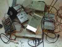
Lambda multiple output power supply (or rather a stack of them)

file.php


Each unit has:

5V @ 20A
12V @ 6A
12V @ 10A
24V @ 16A

All are variable to almost double the output voltage

For 10A charing:

I use two of the above power supplies, each set up for 50V
I set the 24V@16A up to 30V@16A
I set the 12V@10A up to 20V@10A

This gives me an effective 50V@10A
I do the same with the second supply in series to give me 100V@10A


For 16A charging:

24V@16A set up to 30V@16A
12V@6A in parallel with 12V@10A both set up to 20V@16A

This gives me 50V@16A
That goes in series with the other supply to give me 100V@16A

I have 3 or 4 more of those supply's so when I move up to a 20Ah pack I plan to charge in 30 minutes ;)

I think there may be more information in this thread
(though it is dated)
viewtopic.php?f=14&t=6542

-Patrick

EDIT: I did not answer part of the question: The maximum charge current for my cells is "when they get hot". 10Ah Lipo. I used to charge at 1C till you told me I could charge at 2C+. . . :twisted: These are 25C packs so 2C charging is not problem what so ever. When I switch over to A123 you had better believe that I am going to be charing at 4C.
 
i think i found a fet that can handle the higher voltages.

http://search.digikey.com/scripts/DkSearch/dksus.dll?Detail&name=497-5167-5-ND

950 volts at 10 amp.

you should be able to increase the amps by paralleling a bunch of them.

i doubt that many users would be pulling more than 10 a to charge the batteries.

also i doubt that anyone would be putting 900 volts into their bms but it is a nice safety cushion so even the inductive kick from the motor should not be enough to hurt it.

fechter said:
methods said:
So there you go, I did the research for you guys :roll:
The 12V regulator works fine for 24S 100.8V packs but if you do something stupid it will blow out.
I find myself suspecting that a big kickback from the controller could probably do the same thing

Anyhow, it was recomended that I supply my own 12V and now that recommendation has been validated :wink:

Onward!

Good work!
Watch those fingers... You don't want to be touching any live wires at that voltage either. :shock:
I recognized that weakness at higher voltages and corrected it in the next design. With the right parts, should be good up to 300v (but the FET won't take that much).

What are you using to charge at 1kW? That must make your lights dim when you turn it on.

What is the maximum charging current for your cells? You should get some fast charging times.
 
ejonesss said:
i think i found a fet that can handle the higher voltages.

http://search.digikey.com/scripts/DkSearch/dksus.dll?Detail&name=497-5167-5-ND

950 volts at 10 amp.

you should be able to increase the amps by paralleling a bunch of them.
That one has an on resistance of nearly 1 ohm, which means it would need to dissipate nearly 100 watts at 10 amps. That would take a really big heat sink.

With an IRFB4110, rated at 100v, you should be good for pack voltages up to around 200v or more since the FET will only 'see' the voltage difference between the charging source and a fully depleted pack's voltage. At 20 amps, the 4110 will need to dissipate less than 2 watts. To use higher voltage rated parts, you would need parallel FETs to bring the on resistance down to a reasonable level.

methods:
Do those Lambda power supplies have linear current limiting? Some supplies will go into shutdown or hiccup mode if the current reaches the limit.
At very high charge rates, cell heating can be an issue. A weak or stressed cell could go poof. Keep those packs away from combustible materials when charging....
 
can the resistance be lowered by paralleling fets too?

in theory paralleling resistors lowers the resistance and increases the wattage.


fechter said:
ejonesss said:
i think i found a fet that can handle the higher voltages.

http://search.digikey.com/scripts/DkSearch/dksus.dll?Detail&name=497-5167-5-ND

950 volts at 10 amp.

you should be able to increase the amps by paralleling a bunch of them.
That one has an on resistance of nearly 1 ohm, which means it would need to dissipate nearly 100 watts at 10 amps. That would take a really big heat sink.

With an IRFB4110, rated at 100v, you should be good for pack voltages up to around 200v or more since the FET will only 'see' the voltage difference between the charging source and a fully depleted pack's voltage. At 20 amps, the 4110 will need to dissipate less than 2 watts. To use higher voltage rated parts, you would need parallel FETs to bring the on resistance down to a reasonable level.

methods:
Do those Lambda power supplies have linear current limiting? Some supplies will go into shutdown or hiccup mode if the current reaches the limit.
At very high charge rates, cell heating can be an issue. A weak or stressed cell could go poof. Keep those packs away from combustible materials when charging....
 
ejonesss said:
can the resistance be lowered by paralleling fets too?
in theory paralleling resistors lowers the resistance and increases the wattage.

Yes, you can put about as many as you want in parallel. It would take about 20 parallel of the 950v ones to get the same on resistance of a single 4110. Having more parallel units will spread out the heat dissipation, so with enough of them, no heat sink would be needed. For very high power applications, this would be a good option, though I would try to find a FET with a lower on resistance and sacrafice some voltage rating.
 
that about 2 fets in series would that double the voltage? i know it is going to double the resistance.

of course it may not matter since pulsing makes them handle more amps and maybe more volts?


fechter said:
ejonesss said:
can the resistance be lowered by paralleling fets too?
in theory paralleling resistors lowers the resistance and increases the wattage.

Yes, you can put about as many as you want in parallel. It would take about 20 parallel of the 950v ones to get the same on resistance of a single 4110. Having more parallel units will spread out the heat dissipation, so with enough of them, no heat sink would be needed. For very high power applications, this would be a good option, though I would try to find a FET with a lower on resistance and sacrafice some voltage rating.
 
fechter said:
Do those Lambda power supplies have linear current limiting? Some supplies will go into shutdown or hiccup mode if the current reaches the limit.

These Lambda power supplies are the shizzle.
If you load one of the circuits down, say the 12V@10A, it simply gives you 10A constant all the way down.
If you dead short any of the outputs it will simply go into safety mode

1KW continuous is all these can really put out. When I start to go over that (say when I try to charge at 100V@16A) you can actually hear the supply crying. The different boards start to buzz and resonate as they reach their limits. Some times it will pop the protection when I plug it into a near dead pack.

This is not a problem though. . . And here is why :mrgreen:

6KW werf.jpg

I could easily do 100V @ 60A with all these
When I built my house I ran 20A "Home Run" lines to nearly every box.
At any place in my house you can plug into a 2 gang box that has a 20A circuit on EACH side.
This means that I can pull 4KW no problem

-methods
 
methods said:
fechter said:
Do those Lambda power supplies have linear current limiting? Some supplies will go into shutdown or hiccup mode if the current reaches the limit.

These Lambda power supplies are the shizzle.
If you load one of the circuits down, say the 12V@10A, it simply gives you 10A constant all the way down.
If you dead short any of the outputs it will simply go into safety mode

1KW continuous is all these can really put out. When I start to go over that (say when I try to charge at 100V@16A) you can actually hear the supply crying. The different boards start to buzz and resonate as they reach their limits. Some times it will pop the protection when I plug it into a near dead pack.

This is not a problem though. . . And here is why :mrgreen:

View attachment 2

I could easily do 100V @ 60A with all these
When I built my house I ran 20A "Home Run" lines to nearly every box.
At any place in my house you can plug into a 2 gang box that has a 20A circuit on EACH side.
This means that I can pull 4KW no problem

-methods

Hey Methods, Does these psu are the one i found on ebay for you and that i shared the link few months ago?

if so.. that 's great to see you like those! :mrgreen:

My charging station are one of 1500W (50V 30A) for paralleling 2x 50V pack for recharging

The other is my great find on ebay... a powerone of 0-100V 0-10A.. ... total 1000W that i use full load!!!

Doc
 

Attachments

  • 1400W charging !_1024x768.jpg
    1400W charging !_1024x768.jpg
    82.7 KB · Views: 2,851
  • P1060085_1024x768_1024x768.jpg
    P1060085_1024x768_1024x768.jpg
    121.5 KB · Views: 2,851
Doctorbass said:
Hey Methods, Does these psu are the one i found on ebay for you and that i shared the link few months ago?

Actually these power supplies come from a high-tech firm in Santa Clara.
As I understand it they have a giant bin in the back that they fill with expensive components.
If a component was part of a system that had a problem, everything has to be thrown away for safety.
(High consequence systems) I guess it is cheaper to throw it away then to re-qualify it.

My friend brings me these just to see my eyes light up.

-methods
 
i thought of a better idea instead of a latch would having a delay before releasing the lvc work?

maybe something that waits until the voltage recovery is over?.

the problem is if you have open throttle and the lvc kicks in it would be like flicking the light on and off.

each time you turn a light on the shock to the bulb shortens the life of the bulb.

i know that the controller's lvc has a delay of like 1 or 2 seconds before it comes back on so you have time enough to release the throttle.

the brake inhibit does not have a delay (i do not believe)


GGoodrum said:
In any case, the oscillation is actually a desirable trait, in my opinion, so I'm not too interested in adding any sort of latch that has to be reset. That would be a pain.

-- Gary
 
jonesy, why not go back and read how the LVC idea was developed about a year ago, which lead to them deciding to build this BMS, in the way it is now laid out.

you would learn a lot from that. it is in xyster's build thread from last year, but i can't remember exactly when bob and gary kinda decided to go this way, outside of the fact that there are no fets in the output to soak up power like other designs. maybe somebody else remembers. it seems like it was 1/3 into the thread, but the whole thread is worth reading if you haven't been there before.
 
i was wondering when charging other lithium cells can the charge be removed suddenly when it reaches a given voltage safely like what would happen if a relay was used to turn off the charging?

because i think i can design a simpler charger circuit that uses just a TC54VC4302EZB to detect when the cell gets full and then turns off a relay (cuts of at 4.3 unfortunately one that cuts off at 4.2 could not be found in stock at mouser).

a transistor to drive a relay and a relay to turn off the charging.


and a 2.5 volt TC54 for the lvc with a transistor and relay.
i want to work with moli cells on this project and that why i was wondering if it is safe for the cells to suddenly cut off the charge verses taper off.

also ggoodrum do you know when you will be restocking the bms boards again and selling the new one that will be able to handle the other lithium cells?

also parts do i have to change on the current bms to make it handle the emoli cells?

thanks
 
Eric, you don't want to just cutoff the charger when the voltage reaches some point. With all Lithium batteries, and even with SLAs, doing this cutoff, as you propose would leave the cells only about 80-85% full. What all Lithium and SLA chargers do is implement a Constant Current/Constant Voltage (CC/CV) charging profile. What that means is that the charger initially holds the current at whatever the max is that it is designed for, and it lets the cells determine the voltage, which will then slowly start to rise. The voltage rises because it becomes harder for the cells to accept the same amount of current as they become fuller. When the cells get to about the 85% full level, the voltage starts rising at a much higher rate. For LiFePO4 cells, this "knee" in the voltage rise rate "curve" is at around 3.65-3.70V. For LiMn/LiCo, it is 4.2V and for SLAs, it is around 2.40-2.45V.

In order to fully charge the cells, past the 85% level, the charge switches to the CV mode, where it holds the voltage at the cutoff point, and then the current slowly will drop, at roughly the same rate that the voltage rises in the CC mode. When the current drops to a under a hundred milliamps, or so, the cell is about as full as it is going to get.

What the BMS does is that it allows each cell to basically have its own CV mode, so that if the cells end up with slightly different capacities, or become otherwise unbalanced, they can each reach a 100% charge level at their own pace. When all the cells reach this point, the charge current will be cutoff completely, via the SCR, until the system is reset.

With the holidays, my time hasn't really been my own, so I haven't completed the layout changes for the latest version, I'm actually working on those changes today. Part of the delay is because trying to switch to a slightly lower-priced opto chip replacement for the ILD2 causes major surgery to be required to the layout, due to a different pinout. With 3.0V versions of the through-hole TC54s available at Digikey now, we really don't need to do a complicated set of voltage divider resistors/jumpers in order to implement a version that will work with LiMn/LiCo-based packs. All you need to do is substitute the 3.0V TC54s for the 2.1V versions and use different value resistors for the voltage dividor used by the LM431s

The only other changes I'm doing are the addition of a couple parts in the voltage regulator section, so that this board can be used with higher voltage (100V...) setups, and the increase in the diameter of the shunt transistor holes so that the larger parts methods is using in his version can be used. Maybe what I will do is forgoe doing the ILD2 replacement, for now, and finish up the other changes so that I can get more boards made. That actualy works better for me, as I still have enough ILD2 chips to do the boards for my own packs.

-- Gary
 
Gary,
That 100V (24s LiMn) with 3.0V cutoff may interestet me.. as you know already, i'm interested about getting one of those great BMS you did and is working on!

I still didn't got anymore 28V dewalt for you, but i keep an eyes on them for you like you asked for! :wink:

Doc
 
GGoodrum said:
...and the increase in the diameter of the shunt transistor holes so that the larger parts methods is using in his version can be used. ...

How many volts over HVC do you generally have to set the power supply with the 500ma shunts to get consistent shut-off?

-methods
 
thanks i will wait for your new bms to come out that will handle other lithium cells.

i was thinking somewhere there was a mod where you changed a couple resistors to the existing bms to make it handle a charge of 4.1 to 4.2 volt range and an lvc of 2.5 v.

because since my main project is 48 volts i have 2 unused segments left from the bms board that i could get the parts for so i can try out the moli cells i pulled from an old milwaukee v28 packs i picked up from a local battery recycler.


GGoodrum said:
Eric, you don't want to just cutoff the charger when the voltage reaches some point. With all Lithium batteries, and even with SLAs, doing this cutoff, as you propose would leave the cells only about 80-85% full. What all Lithium and SLA chargers do is implement a Constant Current/Constant Voltage (CC/CV) charging profile. What that means is that the charger initially holds the current at whatever the max is that it is designed for, and it lets the cells determine the voltage, which will then slowly start to rise. The voltage rises because it becomes harder for the cells to accept the same amount of current as they become fuller. When the cells get to about the 85% full level, the voltage starts rising at a much higher rate. For LiFePO4 cells, this "knee" in the voltage rise rate "curve" is at around 3.65-3.70V. For LiMn/LiCo, it is 4.2V and for SLAs, it is around 2.40-2.45V.

In order to fully charge the cells, past the 85% level, the charge switches to the CV mode, where it holds the voltage at the cutoff point, and then the current slowly will drop, at roughly the same rate that the voltage rises in the CC mode. When the current drops to a under a hundred milliamps, or so, the cell is about as full as it is going to get.

What the BMS does is that it allows each cell to basically have its own CV mode, so that if the cells end up with slightly different capacities, or become otherwise unbalanced, they can each reach a 100% charge level at their own pace. When all the cells reach this point, the charge current will be cutoff completely, via the SCR, until the system is reset.

With the holidays, my time hasn't really been my own, so I haven't completed the layout changes for the latest version, I'm actually working on those changes today. Part of the delay is because trying to switch to a slightly lower-priced opto chip replacement for the ILD2 causes major surgery to be required to the layout, due to a different pinout. With 3.0V versions of the through-hole TC54s available at Digikey now, we really don't need to do a complicated set of voltage divider resistors/jumpers in order to implement a version that will work with LiMn/LiCo-based packs. All you need to do is substitute the 3.0V TC54s for the 2.1V versions and use different value resistors for the voltage dividor used by the LM431s

The only other changes I'm doing are the addition of a couple parts in the voltage regulator section, so that this board can be used with higher voltage (100V...) setups, and the increase in the diameter of the shunt transistor holes so that the larger parts methods is using in his version can be used. Maybe what I will do is forgoe doing the ILD2 replacement, for now, and finish up the other changes so that I can get more boards made. That actualy works better for me, as I still have enough ILD2 chips to do the boards for my own packs.

-- Gary
 
I hope Fechter could help me with my BMS 4 cell v.2.2 board from TP-packs I have built.
There is one big Problem with the shutdown process.
All leds lit and I am reading from ground to pin 7 of the opto's 12V and on pin1/ pin2 ~1V. But the opts don't turn the leds off nor the red led goes to green!
Shorting pin 7 and pin 8 of one of the optos the main led turns green. It seems that the optocooplers don't work as they should!
I also checked the auto shutoff feature, when I bridged the control ground to the all shunts' line - it works! :?
 
there is a delay of up to a minute before it turns off.

with no cells connected does the board eventually shut off ? if so then it is not the board at fault.

minute 20 for the leds to come on fully and another 40 seconds or so to turn off. (may vary board to board (mine is 16 cell 48 volt))


manfred59 said:
I hope Fechter could help me with my BMS 4 cell v.2.2 board from TP-packs I have built.
There is one big Problem with the shutdown process.
All leds lit and I am reading from ground to pin 7 of the opto's 12V and on pin1/ pin2 ~1V. But the opts don't turn the leds off nor the red led goes to green!
Shorting pin 7 and pin 8 of one of the optos the main led turns green. It seems that the optocooplers don't work as they should!
I also checked the auto shutoff feature, when I bridged the control ground to the all shunts' line - it works! :?
 
Back
Top