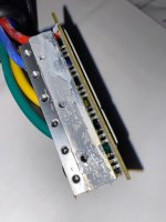
Kapton's primary disadvantage in heatsink use is that when it's thin enough to be good for this purpose, it's really fragile and can be punctured by any surface defects in the FETs, such as the edges of the tabs, or if the installer didn't brush off any particulates on the back of them or the surface of the heatsink itself, etc. At that point it allows electrical contact which is what it is there to prevent.
It's not normally a problem, with good manufacturing techniques, but they clearly don't use those in the factories that make this stuff, given the problems we see, such as the unused solder clearly left on the bottom of the board (which could easily short out major electrical paths when it vibrates loose and begins rattling around the casing, destroying the controller).
If you do need to replace it, you can use things like this
https://www.google.com/search?q=Laird+TGARD+500&tbm=isch
A bigger problem with the specific unit you picture there is the heatsink bar itself, vs the casing it connects to--it is clear from the hugely excessive amount and placement of the thermal paste visible on the bar that it does not fit properly against the casing, so it will not be able to properly transfer heat out of the bar and into the case so it can radiate into the air.
Thermal paste is only intended to fill the tiny airgaps in the scratches and surface defects of the mating surfaces of the heatsink bar and case, not to fill gross airspaces like they use it for here (and in most cheap ebike controllers).
Without good metal-to-metal contact for as much surface area as possible, there will be fairly poor thermal conductivity even when the thermal paste is new. As it ages and dries out, this will get worse and worse, because there will be more and more air between the two metal pieces, and heat will take longer and longer to transfer from the bar to the case and thence to the outside air.
There is a process called lapping, which I would recommend to use on that heatsink bar on both sides, to make it as perfectly flat as possible, to improve it's mating ability and thermal transfer to both the FETs and the case. Then lap the inside of the case so the area the bar mates to is also as perfectly flat as possible.
Once that's done, then use a *tiny teensy weensy* amount of thermal paste to only fill in the scratches on the bar and case where they mate (and same for FETs to bar), so that as much actual metal of the case is directly in contact with actual metal on the bar, and is not blocked by air or thermal paste.
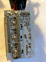
Regarding solder on the main busbars of the FETs, there may be plenty. Since they cover the copper traces completely (possibly even overhanging their edges) you'd need to use a camera that can see very closely and from the edge of them to see underneath to tell if solder is correctly flowed between the copper and the bars.
Solder on the *outside* (bottom, sides) of the bars is irrelevant. The bars provide the conductivity, as long as they are correctly electrically bonded to the copper traces leading to the FETs.
It might be better if the bars extended all the way to the large battery-input traces. If you find it's a problem, you could add solder between the ends of the bars and those traces, but it will take a huge amount of heat to do this, and that will be passed into the FETs and all the parts on the PCB near the busbars. So doing it with as large a tip as you can get (like nearly pinky-sized) on a high-wattage iron will be easier on the components.
You'll need to be careful not to keep heating it for very long partly to prevent heat damage to those parts, but also so you don't accidentally unsolder the bars from the copper traces (or cause the traces to separate from the PCB).
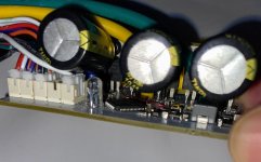
As long as you don't need to repair any components under them later, you can use silicone to glue the capacitors down to the PCB; it'll secure them well enough.
But if there is room on the PCB for the whole capacitor base, it would be better if you can unsolder them, and push the leads all the way thru the PCB so the cap mounts vertically on the board, it's base actually against the PCB, because this gives the shortest leads which is best electrically and mechanically. The only problem with doing this is it requires modifying the controller case to accommodate the capacitors sticking up beyond the top of the case. If the case is the type that slides on from the end, you'd have to cut slots in the top panel to allow it to slide past teh caps without touching them (so it doesn't damage the casing of the caps).
While they're unsoldered, you can also replace them with low-ESR caps if they are not already that type.


")