Friction drive BMX in the making......

cajunjay

1 W
Joined
Apr 22, 2011
Messages
63
Location
Leicester
Hi guys

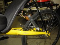
I have put this friction drive bmx together but need some help/advice to get it working properly. I think the stem Ive used is too short as the motor hangs pretty far away from the tire. When I give it some throttle the motor jumps towards the tire but slips rather than climbs the tire. I want to try keeping the motor in the current position.

Im using a cheap 120a esc and using it with a normal ebike twist throttle, run at 22.v volts.
 

Attachments

  • bmx2.gif
    bmx2.gif
    244.8 KB · Views: 1,533
I don't mean to rain on your parade, but are you sure you are doing this in a wise way? Some gas powered bikes use friction drives. However, they have a consistent pressure pushing from above with the motor often aiding (gravity). Even in that, they still experience slippage, and their tread goes way more quickly. If ever you get your wheel wet, I'd be surprised if you got much energy to the wheel if any at all.

You might consider something like a mid drive, it looks like you are half way there : P.

I know that it sucks spending lots of cash on this, but they say you get what you pay for. It looks and sounds like this might not be a very great setup. I bet you can find cheap enough chain and sprocket kits that would deliver all the energy to the wheel.
 
You'll need to :
- add a spring to take the weight of the motor
- change the geometry so the motor wants to climb the tire. Test it by putting the rear brake on, lightly lifting the motor to touch the tire, then rotate the motor. If it tries to bite in to the tire, all good. If it tries to slip you need to change the geometry to have the swingarm pivot/ motor axle / wheel axle more in line.

By eyeballing the geometry I would first move the motor mounting position closer to the swing arm axle. Then do the climb test again. Next would be to move the swing arm pivot closer to the seat tube.

This is very close to my design, so feel free to copy the geometry for your own use. My manuals also may help in understanding the geometry. Check the link in my signature.

Good luck !
 
+1 with Adrian's comments.
basicly you need a shorter swing arm fro the motor mount, and a spring to balance most of the motor weight.
Also check out the controller mods that have been posted ..extra cap's on the feed wires, and optimum settings to avoid losing syncronisation.
What motor are you using ? (size, Kv, etc )
 
Thanks for the tips Adrian and Hillhater.

The motor Im using is 200kv 63mm

So basically I need to shorten the actual motor plate firstly as it is far too long especially when compared to the commuter booster. Then I will try the test where I need to find the right geometry to get the motor to climb the tire instead of just slip.

As for making the mount on the seat tube closer to the seat tube Im a bit confused I would have thought it would need to be longer. Does it matter what angle the motor plate is hanging as with a commuter booster it seems its hanging directly downwards whilst mine would need a spring for support as it would be holding all of the motor weight as the motor hangs far from the tire naturally.
 
The swinging action of the starting torque of the motor will only affect the motor on start-up, once running, it will just hang there. If the swinging-arm was shorter, you might be able to adjust it so that the is slightly wedged against the tire. Perhaps move the tire farther back as much as possible and shorten the arm as much as you can. Intsall an arm-rest under the swinging arm so that it is near 20-degrees away from perpendicular to the tire, and adjust everything so that the motor-shell is almost touching.

The motor starting torque will draw it into the tread, the spinning tire will pull it in farther, and once fully engaged, it must be near perpendicular to the tread (swing arm in line with the motor shaft and wheel axle). You will need some type of stop to prevent the swing arm from rotating any farther than perpendicular.
 
Yep shorten the motor plate/swing arm first, but looking at your seat tube clamp you are going to be limitted by clearence, and may not get it short enough before your motor basshes into the clamp.

The Commuter Booster has a spring to take the motor weight, the dead stop should not actually be taking any real weight. Your placement will just needs a stronger spring force as the motor plate needs to be more horizontal.

The angle of the motor plate is crucial, but it is all about the angle between the pivot point for the motor plate, the contact point between motor and tire, and the axle of the rear tire. Just find an image on one of my drives installed and look at the angles, then rotate them all around to where you have yours mounted, and you will get a pretty good idea of the angle the motor plate needs to be at to allow the motor to climb the tire properly.
 
That wouldnt work as the motor will then not reach the tire.

Ive tried a few variations but all points to shortening the actual motor plate and also making/using a different bracket/mount for the seat tube. :(

I tried what Adrian said and did notice that the motor grabs the tire best at the 11 o'clock position but this means the whole drive needing to be moved onto the actual seat post and modified.

p.s

Thanks spinningmagnets makes things more clear now :D
 
Cajun


It looked like it would reach in your picture .. to bad , I hope you get it figured out.. that should be a fun ride ..


There is a place for friction drive in ebikes for sure ... Just keep it simple :) ... Bill
 

Attachments

  • Picture 045.jpg
    Picture 045.jpg
    73.8 KB · Views: 1,342
Back
Top