GCinDC's Giant DH Comp

Great to see it back together and nearly done. Behold, for it has risen from the dead! You should call it the black zombie :p
I must have missed it earlier but how are you planning to mount the controller ? The little boards go in the box I take it but is there room for the controller too ? Or will it sit in that little cut out scoop at the the head tube end of the triangle?
 
Bike is looking sweet!! And all this time I thought my bike was a resurrection haha. Yours came back to life from an inferno. Can't wait to see how that new controller/bms system performs. They should be paying you for your quality assurance.

I'm definitely looking forward to seeing some video!
 
20130623_195645.jpg

Deserves reposting :)
Crank it out Greg for every one posting the must be 10 or so keen followers hoping to see you get back on the lipo. Combined with your new (re)found quads you'll be blitzing the DC traffic!
Peace
 
I knew you would try to refurbish the bike, but I never knew you would do this good of a job. :p
It's nice to see you get back on the ole ebike saddle. Speaking of which, was the last time you road an ebike the night before the fire?
 
thanks guys. it's fun to share the process. and i appreciate all the suggestions.
Trackman417 said:
I never knew you would do this good of a job. :p
after big fires, seems wise to change ways a bit...
was the last time you road an ebike the night before the fire?
i rode a floppy old friction drive to the metro a couple times. last ebike commute was 3/20/13:
[youtube]xIA0kbLiNPs[/youtube]
did i ride like that? gollie... :mrgreen:
 
brakes done. so much nicer to adjust stokers than using washers! crappy pics. garage was boiling..
20130624_214040.jpg

20130624_213957.jpg

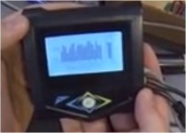
fooled around with controller placement etc, need to rig up a mount. but display fits perfectly here.
20130624_220201.jpg


plus some odd jobs on sat:
[youtube]o5cSs3s5TB4[/youtube]
 
bracket shape and position is awesome for my bars, but it's actually a bit tricky to bolt on.

i measure the gap at 6.67mm:
20130625_174246.jpg


but the nut was a bit big to force in there for plastic i thought:
20130625_174302.jpg


so i skinnied them a bit:
20130625_174728.jpg

20130625_174526.jpg


and then with some needlenose type pliers, it's easy to attach the bracket in the deeper slot.
20130625_175500.jpg
 
GCinDC said:
did i ride like that? gollie... :mrgreen:
hah I thought that too after all my time crook. When I first got back on the bike I remember thinking "wow this is too fast, this feels unsafe to go full throttle" then a week later I was back to full throttle straight out of the garage door and wanting more

GCinDC said:
garage was boiling..
you should have added a warning, I wasnt expecting to see topless footage. I saw nipple for gods sake! :lol:

GCinDC said:
no time to edit this
I watched the first few minutes then let it play in the background for another 20 :p
It certainly looks like a sweet system.
 
Cant wait till you get the bike running man. I am super excited to see what the minee has in store for you.
I never knew other people pronounced lipo other ways :? . I pronounce it as lie-pi not as lip-o. Eh good on you mate, havent gotten past the first 3 minutes of video to critique anymore though, not sure you want me to, so I will stay nice and quiet from here on out :wink: .
 
Hyena said:
A second smooth/linear regen throttle is something that's sorely missed from other controllers. I'll be interested to hear just how much regen force you can get from it. It'd be cool to be able to do away with rear brakes and just have regen. You could have a cable brake lever with just 2" of cable on it, a magnet on the end with a hall sensor glued to the sheath and that's one let cable/line that needs to leave your bars :)
i tried to open the throttle to solder in the pigtails but it wouldn't come apart by removing the screws alone. anyone know how to get these apart?

in the meantime, i clipped the wire and with 3" extra line, i'm feeling sloppy... :lol:

gotta check the wiring but have a feeling the throttle wires will mate up this way. not sure what to do w/ the button.
20130625_222034.jpg

and now to find a nice hall sensor for the brakes...
 
I have same as your throttle with button.

It's for cruise button that what is. I got the throttle with the button from Paul from em2ev.com...... :)


GCinDC said:
not sure what to do w/ the button.
 
GCinDC said:
i tried to open the throttle to solder in the pigtails but it wouldn't come apart by removing the screws alone. anyone know how to get these apart?
My throttle holds together through 4 plastic clips inside. To get it apart I just need to pull it a bit harder.

Tomasz
 
Hyena said:
It'd be cool to be able to do away with rear brakes and just have regen. You could have a cable brake lever with just 2" of cable on it, a magnet on the end with a hall sensor glued to the sheath and that's one let cable/line that needs to leave your bars :)
with KElly controller, when I putt the regen mode to the max I'm too much pushed on the bar @30kph or 60kph..., so I had to downgrade it to half the max...I didn't wired a throttle yet to it but i stop really hard...it almost make the back wheel drifting...feel like I have the ABS @full regen engaged when realeasing the throttle...sweet touching the rear break make it drift...
 
keep trying to do some wiring and can't find my damn soldering iron. i could have sworn it survived, but maybe it got tossed (along w/ my hall sensors...) :roll:

i installed a friend's old AC in the garage and am sooooo happy. now it's like a dream! before i'd sweat after 5 min of doing nothing - hence the regrettable nipple shots... no more!

so fooling around w/ controller locations... i don't love it on the bottom tube near the bracket. :?

it's small, but i can't fit it on the rear swing arm.

sticking it on the forks where others have the pelican packs is definitely doable, but the phase wires would be pretty long then. :|

i wouldn't put it in the enclosure w/o fan, and with some cutting, i could acutally fit it!
20130627_165422.jpg


or, hell, the damn batts fit this way, despite all my prior geometry tests:
20130627_170219.jpg


i'm just thinking out loud. settle down.... :p

this bike will be running w/in a week, i promise. maybe this weekend. :twisted:
 
I would say modify your existing casing. You put too much time and effort in that to toss it.

Or

just put it up front, on the fork, so you don't have to worry about cooling it down. That's what I plan to do. Are there any problems associated with having long phase wires? too much resistance? loss of performance?
 
GCinDC said:
i wouldn't put it in the enclosure w/o fan, and with some cutting, i could acutally fit it!
Better still, why not remove it from its case, make an aluminium side panel for your FG box and bolt it directly to that ? It'll have good heat dissipation with a flat plate that size and it has the added benefit of keeping the indices of our box dry and out of the grime, and minimise wiring mess too.
If it has to fit in that orientation just make a L plate that bolts to internal heatsink bar and to your side cover.
 
I remember reading on the adapt Minee build thread that since it was a sine wave controller the parts wont heat up as much? That was one of the first things they mentioned in the thread, everything becomes more efficient so less heat is made. I would run it in the triangle box first and keep close tabs on the temp just to be sure, before I start gouging out your fiberglass box or put it anywhere else.
 
nicobie said:
Why not just but it on the back side of the seat post tube. I doubt the the rear suspension has that much travel to make a problem.
like this?
file.php

how quickly we forget... from here.
file.php


i like the looks of my new enclosure too, so far, but if it ain't gonna fit the business...

i wasn't going to say anything, lest i face your wrath... :lol:

but with a snip, snip here:
20130627_215744.jpg

and a bend, bend there:
20130627_220510.jpg

20130627_220851.jpg


presto, a solid box, with a flip open top, and an easy way to worm-clip to the top/seat/bottom tubes..
20130627_223934.jpg

and the controller slides in right there exposing bolt holes on each side of the top tube, needing only a custom bracket.

don't look as purty, no sirree, but something can be done about that...

just thinking out loud...

and i'm not doing any series/parallel connectors this time. andrey convinced me. and the bms cell voltage display is pretty sweet (from 31:36 of bms vid)!
bmscellvoltages.jpg
 
got a soldering iron finally, and anxious to build the pack, but my plan of halving the one 8s pack into 2 x 4s packs is stymied because i can't solder to the tab... :(
20130629_090454.jpg

thought it might have varnish so i sanded the side:
20130629_090942.jpg

then used the dremel:
20130629_091254.jpg

and i split the 10 fibers on each side, clamped them to the tab, and soldered it up nicely, but it slid right off. :eek:
20130629_092858.jpg

now researching, it appears the tabs are aluminum and really solderable. and i may have damaged the cells by heating the tab for too long! :x

kinda important to have good conductivity off the new lead. might need to get proper 4s packs...

now some highlights from the week pedaling the road bike:
[youtube]hCTiv-MHVOU[/youtube]
 
Back
Top