geared kona dirt jump frame SOLD

flyinmonkie

10 kW
Joined
Oct 8, 2008
Messages
753
Location
NZ
Ok, so I know I started a thread for this a while back, but I have enough parts to start building now. Low down on the design....

A dirt jump frame - Kona Roast
600w currie brushed motor over volted to be 1000w or so
Lipo bats most likely at 44.4v
Final drive will be bike chain through the derailleur and 3 gears
Pedals separated from the motor drive with a splined eno
Motor mount and gear reduction designed by me

I think that takes care of most of it. I am still deciding on a controller and throttle and throttle interface (to protect the lipos)

I have the following

Bike
Motor
Mount and reduction (need jack shaft)
Eno (Luke is splining it)

Need

Batteries (waiting for HK)
Controller
Throttle
Throttle interface

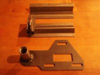
Below are some pics of the motor mount and reduction and motor. It has been based on Matt's RC drive, but to fit my motor. Like Matt's, it is adjustable to fit on another bike if I decide to move it or in a different direction. As I start to add parts, I'll post more pics.

Clay
 

Attachments

  • P7130053.JPG
    P7130053.JPG
    39 KB · Views: 9,605
  • P7130054.JPG
    P7130054.JPG
    40.4 KB · Views: 9,605
  • P7130055.JPG
    P7130055.JPG
    38.2 KB · Views: 9,605
  • P7130056.JPG
    P7130056.JPG
    33.2 KB · Views: 9,605
  • P7130057.JPG
    P7130057.JPG
    38.9 KB · Views: 9,605
  • P7130059.JPG
    P7130059.JPG
    39.1 KB · Views: 9,605
  • P7130061.JPG
    P7130061.JPG
    46.7 KB · Views: 9,605
*suscribed

Look forward to watching this one unfold...great start with the drive/jackshaft, some neat welds there

KiM
 
Tell me about it Kim. Wish I had those skills, I had it made up for me. The guy does most of his work on stainless. Would have been really cool in all stainless, but to expensive.

Clay
 
Hey, I like it! I feel honored to be mentioned in your thread. That drive looks really good!

Looking forward to this thing coming together.

Oh, other than LV cutoff to make sure you do not overdischarge the pack, you do not need to worry about protecting the lipos. They can put out more current than other chemistries. :D

Matt
 
Thanks guys,

Knoxie
I was running it at 36v with good results and won't be going more than 44.4v, but I'll keep that in mind. It never got too hot to touch at 36v of sla's even on the hills.

Matt
LVC is what I am worried about, but I am looking at a controller that takes a range of voltages and currents, so I want to protect it as well. I think either the throttleiser or fetchers box would be better than the cheap controller at managing those. No worries about the mention, I'm sure I'll mention you again. Your work is an inspiration for all of us. You have a great way of making things simple, effective, and elegant and I strive to do the same. A truly professional solid build is what I am going for. As well as functional in a hilly area. I love the high power builds and pushing the envelope that guys are doing. But, I want to take some of those ideas and apply them to less powerful and more affordable parts to make a bullet proof commuter for a reasonable price.

Colby
Thanks. Bike pics will be coming in the next couple of days. Also the start of motor placement and layout. Keep tuned.

Clay
 
I just got notice that HK has batteries back in stock. I have been looking at the Zippy Flightmax 5000 6s1p 30c, but they also have 5800 6s1p 30c. Any reason to not go with the higher amp hour bat?

Clay
 
Bear in mind, the Throttlizer and Fechter's box are both designed for RC drives. They output a PWM signal. They are not compatible with a standard sensored or brushed controller.

Other than that, I see no reason why this setup will be anything but fantastic!

Matt
 
Cheers Matt,

Good to know. I will look at my controller options and see if I can get one with a programmable LVC suitable for my motor. Any ideas out there?

Clay
 
Tomorrow will be work on bike day. I will be drilling the bolt holes needed in the motor mount and hopefully painting it. I'll get some bike shots as well and post them. I also need to source a jack shaft, so I may do that after I take some measurements. I also have to set up the bike (adjust hubs, brakes, derailleur, headset, etc).

I am leaning towards the following controller and one of ggoodrum's LVC boards and a hall effect throttle.

YK43B - Technical Parameters

Rated Voltage: 24 to 60 Volts
Rated Current: 30 - 100 +/- 1.0 Amps
Rated Motor: Up to 1000 Watts
Conversion Efficency: 95%
Under Voltage Protection: NONE
Speed Control: Hall Effect Throttle (1 - 4 Volts) Included with controller.
Dimensions: 105mm x 115mm x 48mm (L x W x H)

Clay
 

Attachments

  • controller.gif
    controller.gif
    45.1 KB · Views: 10,682
Well, I didn't get as much done as I wanted, but I made some headway. I figured out that I can't mount the motor where I wanted, below the bottom bracket. I am going to mount it on the top of the down tube. I shortened the mounting bracket and will bolt it to the water bottle mounts and use 2 U-bolts to clamp it to the frame. This will keep everything clear of obstruction and I may get away with a standard width bottom bracket. I should also be able to keep the front derailleur and three pedal gears. I haven't checked my chain line from the motor yet as I don't have my jackshaft. I'm sure I am going to run into the chain stay, but I should be able to direct the chain over it. Oh, I was wrong about the frame as well, thought it was a stab, but it is a roast. Below are pictures.

Clay
 

Attachments

  • P7160066.JPG
    P7160066.JPG
    49.1 KB · Views: 9,373
  • P7160068.JPG
    P7160068.JPG
    59.7 KB · Views: 9,373
  • P7160069.JPG
    P7160069.JPG
    48.9 KB · Views: 9,373
  • P7160070.JPG
    P7160070.JPG
    51.3 KB · Views: 9,373
  • P7160071.JPG
    P7160071.JPG
    53.9 KB · Views: 9,373
Hey fm,

sweet, this is looking really nice, i'll be interested to see what you get from that currie motor, driving the crank should work really well with an eno.
keep the pics coming as you go!!

D
 
Hey D,

Thanks. I'm not going to drive the crank though. It will be direct drive to the rear wheel through the rear derailleur with 3 speed for the motor. I'll keep the front derailleur to have 3 pedal speeds as well. The eno will go on the rear hub for the pedals to drive. The drives won't be completely separated at the rear wheel. The final motor drive train will turn when I pedal, but only that one.

I am looking forward to seeing what kind of performance I get as well. I was pretty pleased with it at 36v and a 20in x 4.5in wheel, I just needed gears for the hills. :wink:

Clay
 
The motor bracket is basically sorted now with 2 U-bolts and 2 longer bolts for the water bottle holes. Though looking at the chain lines, I'm not sure the motor will stay where it is. I will be able to get a single pedal speed where it is but may have some issues with the chain stay. When I get the jack shaft I will try some chain lines and maybe move the motor to get a better one. I have some options with this drive, which is why I made it the way I did. More to come once the jack shaft arrives.

Clay
 
Lipo, controller, and throttle are on their way. I also got a Turnigy watt meter to keep an eye on things once it all starts running. I will be going to check on my jack shaft today. Hopefully it is done and I can work on alignment and motor placement while I wait for the rest of the stuff. I have emailed Gary (GGoodrum) to ask about his LVC boards to see if they would work and to see exactly what I need.

That pretty much covers it for parts. I need to get a freewheel for the motor output and finish tuning the bike. Then it is waiting for parts to arrive and figuring out where and how I am going to attach the batteries and controller. More to come soon.

Clay
 
The eno from Luke showed up this avo. Below are some pics. Thanks Luke, err a Luke's dad Mike, according to the accompanying note. No luck on the jack shaft. It should be done early next week. I will push forward on the bike itself. Now that I have the eno I can set up the pedal drive and give that a go. More later.

Clay
 

Attachments

  • P7230054.JPG
    P7230054.JPG
    53 KB · Views: 4,896
Hey guys,

While I am waiting on my batteries to arrive, as well as other parts, I thought I would get a few things cleared up about balancing and charging Lipos. I have read the Lipo care thread from start to finish, but I am still a little confused about putting several packs together to make a bigger pack. Basically, I have 2 5800 Zippy Flightmax 6s1p 30c 22.2v lipos. I want to put them in series to get 44.4v and in the future, I will probably order 2 more to put in parallel to extend my range. I have emailed GGoodrum about using one of his LVC boards, but haven't heard back from him yet.

Basically, when I get the packs do I need to balance the 2 packs together to hook them in series and if so, what it is the best way to do that? Also, I have an imax B6 charger (pictured below). Can I charge both the packs at the same time in parallel with this charger, or do I need to charge them separately? If I can't charge them in parallel with this charger, what charger can? Keep in mind I am new to Lipo and want a simple solution that is easy and safe, preferably off the shelf.

Also, since I haven't heard from Gary, does anyone know if there are any problems with his LVC boards and a brushed motor and controller? Also, with the batteries I have, will I need one or 2 boards to series the packs, and if I get another 2 packs will I need more LVC boards. Lastly, can I get them completely assembled, or are they a kit that I have to solder together?

Thanks guys. Parts will be coming in soon so more build pics soon.
 
For some reason, I didn't get the email, but I just answered your PM. First of all, no problem using the LVC boards with your brushed Currie setup. It still uses a hall-based throttle. Here's how you would connect the LVC opto output:

LVC-Throttle Connections-v4.1.2.png

This shows a 24s setup, with four LVC/parallel adapter boards, and you would just need two, but the idea is the same.

For the pack connections, this is how to connect a typical 12s2p setup:

LVC-Pack Connections-v4.1.2.png

The main leads are paralleled at the total pack level, but the balancer plugs allow the cells to also be connected in parallel at the cell level. When two, or more, cells are connected in parallel, they will equalize to the exact same voltage, and from that point forward, can be considered as one bigger cell. Not shown are the balancer output connections. These can be the same sort of 7-pin JST-XH pigtails like those that come on the packs, but I like to use better connectors and heavier, 18-gauge wire. Usually, I use Molex MicroFit 3.0mm plugs and connectors.

BM Booster-19.jpg

I use matching connectors/pigtails on the balancers we are doing:

6s LiPo Balancer-05.jpg

For your setup, using the 6s charger you already have, you could simply use the 7-pin JST-XH pigtails, one on each LVC board. You could leave the setup connected in series, and simply charge each 6s section separately, but I would add an extra set of charge wires. The last thing you want ot be doing is plugging and unplugging the individual packs, just for charging. You do it once, and you will be looking at MeanWell pricing, just like the rest of us. :roll: :mrgreen:

-- Gary
 
Thanks again Gary. I got your PM and replied. The diagrams are very helpful. I think I have it figured out. I'll make sure to post my wire diagram before I set it all up so you guys can poke holes in it before I burn my house down. :wink:

This waiting for parts is almost as bad as waiting for xmas.

Clay
 
After some debate about my jack shaft size choice (15mm to fit my freewheel adapters), I decided to stick with it. The debate was that it is an odd size and I have to get it custom made. My options where modifying the adapters I have and the bearing tube I already had made up. So, as I said I will get the custom shaft made. If it turns out I have trouble with my bearings, I guess I'll get a new bearing tube and motor mount made. I would like the bearings and jack shaft be easily source able and replaceable, but that may come later.

I am happy to say I have ordered a couple of Gary's LVC boards, and a set of Alex DM24 24" wheels. When it all gets here it will be big time build time. My last big task (other than finding the final motor position) is to decide where and how to mount the batteries. I am debating either in the triangle or on a rack on the back. Not sure how a rack would look on a DJ bike.

Clay
 
Hi FM,

i'm glad Gary posted that too, i'm sure we're not the only ones who don't really get how the bms works.
I wouldn't worry about your custom shaft either, i have a tapered one with keyway for my 11t drive 219 sprocket, might be an idea to have two made at the time tho, nice to have a spare and not much more cost than one, my vote goes for in triangle everytime, best place to protect your packs incase of crash :wink:

D
 
Cheers D. Yeah, Gary has given a very clear picture of how to wire the LVC into the packs and the controller. Makes life easier when you deal with helpful people with good customer service.

Mostly worried about the bearings. They are 14mm id x 24mm od and only 5mm wide. We will see how they hold up.

If I put the packs on a rack on the back, they will be under the rack and between the frame of the rack. The will be very protected wherever I put them.

Speaking of batteries... Mine arrived today along with my watt meter!!! I'd have a pic, but my camera battery is dead. They are so small!! You really don't appreciate it until you are holding one in your hand. It will be so much easier to find a place and mount these compared to 3 18 amp hour 12v SLA's.

Getting excited now that parts are arriving!

Clay
 
+1 props to Gary's post, he always seems to make complicated (complicated to us anyway) electronics understandable
to meat heads like us haha.. I use those boards Gary pictured monkie man absolutely
brilliant idea, i grabbed the Battery Medic booster to also brilliant bit of equipment well
worth the money IMHO

Best of luck...

KiM
 
Back
Top