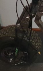
DIY (Mini) ebike/moped -> square tube frame, hoverboard motors - does this look reasonable? Any obvious oversights?

Isn't that what sledgehammers are for? :p
I did try stomping on it with a wedge placed under where i wanted the bend, didnt want to use a persuader as i thought it might crack welds or bend the tubing somewhere id prefer it not to be bent or possibly bulge the side.

Figured cutting and rewelding would be more predictable ;)

Today ive cut axle mounts from hoverboard chassi parts and separated the tubes going into the lower suspension tubes from the crown as well as marking out+centre punching the holes im going to drill in order get the bolts back in them, gonna see about welding them up tomorrow, just need to figure out a good way to clamp them so they stay parallell when welding.

I think ill be doing a couple of spots around the circumference initially so i wont be getting as much warpage as a single larger weld straight off, thats what i did with the second frame half and it got only very minimal warping as can be see in the previous picture.
 
Normally to prevent the parts from warping you'd use a fixture table that holds them rigidly during welding. I recommend watching a couple videos on Fireball Tool youtube channel about this topic.
 
Normally to prevent the parts from warping you'd use a fixture table that holds them rigidly during welding. I recommend watching a couple videos on Fireball Tool youtube channel about this topic.
Ive been following various channels that do welding, dont have a fixture table available so i used a different technique ive seen once or twice (after warping my first attempt by doing large welds straight away), doing smaller spots around the whole joint to hold it before doing a full side of the tubing, it seems to work quite well for my second attempt which remained flat.

I think I have a fork that would work for you.
It would be cheap if you are close enough to pick it up ;)
Stockholmstrakten här, straxt 20 mil till Linköping.

The forks are currently at my work place but if i recall correctly ive cut the front axle to be around 25cm, with a bit extra outside the nuts at each end, how wide are the forks you have? Got a model name/number or pics?

Im heading to the garage today to see about welding the widened crown, if its a total failure i might consider spending most of a day on the road to come visit ;)
(or asking if you would ship em :p)
 
It looks like this:

rdyXbdn.jpg


I dont know, but I guess it is from a scooter.
Just a rough estimate would be about 150-160mm between the dropouts.
Jag tror det var ungefär 150mm mellan de övre benen och 160mm mellan de nedre.
12" hjul
 
rough estimate would be about 150-160mm
I dont think they are wide enough, just the hub on the rim i have is 153mm, the side with the brake rotor mount sticks out something like 15mm more than the opposite, that needs to be addressed by adding in a spacer to make it sit centred, both sides need a bit extra due to having to make space on rotor side for the brake calliper.

Luckily i think my fork/crown surgery was successful, the suspension still moves alright.
Spent quite a bit of time in trying to get the parts clamped together just right before putting the welder to them and then did that spreading-out-smaller-welds-around-the-whole-joint in order to prevent warping before burning those over to make it solid.

At the moment its just the crown and shock tubes welded to a 5mm plate but im going to add some reinforcement, probably A rib running horizontally across it or gussets between the shock tubes and the plate. im not worried about the head tube part as it should be really solid in being welded around on the outside and kinda plug welded through the original holes that went into the shock tubes.

Forgot to take pics but ill see about adding the reinforcement tomorrow and take pics then.
 
Last edited:
Got a reinforcement added in the form of some tubing welded to the bottom of the plate, with quarter moons cut out around the the shock tubes and then welded, preventing bending of the plate itself and stabilizing the tubes.

My welds look decidedly ugly but they have penetration so should be strong.

YFIV6HY.jpeg

gRZ5KPs.jpeg

QyPHv8g.jpeg


Also brought the rear wheel to get an idea of how wide the frame sides should be spaced and after drilling holes for the axle clamps it turned out to be 155mm, i tacked in the lower front side to side connection so the frame now holds its shape with the rear wheel attached.

Did a quick mock up by just clamping the forks to one side of the frame, the fork angle will be a bit steeper than pictured here, overall and i think its pretty close to the design/plan i laid out in blender.
AQ22Vxu.jpeg


Really happy with the progress this weekend.

For next week im gonna bring and cut up the bicycle to harvest the head tube, weld in some more side/side joiners and then look at attaching the head tube.

Ive also realized that the motor wires are very exposed so i will be adding in coverings for those, i think i can cut up some of the tubing into angle plates, or see if there is some laying about at the garage, drill some holes in those and attach them via the outside two bolts on the axle clamps, that should keep the wires safe in case of a tip over.
 
+I'm concerned that more stress members are needed, for safety. Especially the rear drive triangle connection with the rest of the frame.
 
Last edited:
more stress members
Those will come, like i showed in a previous picture.

Ive not been doing a lot this past week, i cut and drilled covers to sit over the cables coming out of the axles to protect against tipover damage to those and cut out the base for a seat.

The plan for the incoming weekend is to be adding in more side to side connectors, like the one in the lower forward section, at the upper rear bend, just above and in front of the rear wheel, at the angle in front of the seat as well as one or two under it.

I may also actually get to separating the head tube from the bicycle frame this weekend.

I think ill probably do some cutting of foam in the evenings this weekend to build up the seat, im getting the fabric for it today.

Aej6JXb.png

I
 
Didnt get anything done last weekend due to a cold snap and working outside+in the shade not being all that appealing.

This week i burned in most of the marked side to side joiners during some slow hours at work.

Tonight ive just finished cutting and glued together foam to build up the rough shape of the seat.

If i drag my ass off to the garage tomorrow i intend to drill holes in the frame and the bottom board for the seat for where they are to join, ive picked up some impact nuts to be embedded in the base board to make the seat easily attach/remove-able from the frame.
When the holes and impact nuts are in place ill be able to join the foam to the base, do some sanding to even out the foam edges and then staple on a pleather sheet.

Ill see about also cutting off/welding on the head tube and the in frame diagonal strenghteners.

Brought a small cutoff of the tube home so i can design, print and test the fitment of some cable clips so i wont be having to use a load of cable ties when routing the motor and lighting wires along the frame, and possibly some mounts for the lights too, tho these will have slots for nuts/bolts to add some clamping force to their attachment.
 
ebike/moped
Just curious. 'bike' implies pedals, and 'moped' is motor-pedal.

Have you checked if what you are building is legal in your jurisdiction? I imagine you probably have. In the place I have lived, that vehicle will require engineering proof that it meets all the legal requirements for a motorcycle, and that a company is willing to issue insurance for riding it (and that you have the insurance when you ride it).
Not everything that goes under the classification of moped has pedals around here, it used to be common but nowdays most dont.

Im building it to comply with feature set for bicycles when it comes to lights and reflectors.
There is a sub class called Elsparkcykel "Electric Kick Bike" which is what we call electric scooters around here, they have the requirements for bicycles, except for not needing pedals and the added limitations of 20kph and 250w max.

I doubt 250w will be enough for going up hills so that is likely going to be exceeded, tho i do intend to keep the speed at 20kph.

Im not all that worried tho, i used to ride a bicycle with one of those chinese bolt on 2 stroke kit motors for my commute to work and just around in general because i liked riding it, did that on an off for a year or three.
The motors are definitely illegal and easily visually identifiable as such because the only legal bolt on 2 stroke motors here are the ones that were sold pre-fitted on bicycles.
Which hasnt happened here for multiple decades, plus that they need to have been insured for all that time.
Which in turn means that there may be no legal bolt on 2 stroke bicycles left at all.
Passed a couple of cop cars going the other way with no issue, im not a 12 year old and i dont drive too fast so i guess the sight of me dont sting their eyes very much.

So me riding something looking like it fits in a legal category will probably sting even less.

As for what got done yesterday:
I drilled the holes for the seat, did final shaping of the foam with a sanding drum, cut the head tube from the bicycle frame, welded it to a plate and welded that to the miniebike.

Had a first roll down the slightly inclined yard at work and beyond sitting on two tubes, rather than a finished seat, that was nice :)
 
Last edited:
I doubt 250w will be enough for going up hills so that is likely going to be exceeded, tho i do intend to keep the speed at 20kph.

Not to contradict, but just to share. I gear down the final drive on my trike (3d in my signature) and with a ShengYi SX2 it goes up 12 degree hills - but not at 20kph. With that motor, it managed about 32kph on the flat.

So, there's hope.
 
Not to contradict, but just to share.
That sounds encouraging, id prefer mine to be on the legal side of things but wattage doesnt feel as important as the speed limit and the tests ive seen of scooters with 250w have not shown them managing to go up hills very well.

I guess those tiny in-wheel scooter motors lack torque tho, likely the hoverboard motor/s im using will have more but then im turning a 13" tire directly.

Either way the controller has options to set max wheel speed and max amperage/which determines wattage separately so i can set max 20kph even if the wattage goes higher than 250.

Im already kinda bummed i hadnt heard about VESCs when i ordered mine, a dual motor controller with regen would have been nice as it would have given me a very easy rear brake.
Will get this running and see how i feel about it, might pick up a different controller if im not happy with this one after the tax return drops, i should be getting somewhere in the neighbourhood of 3k usd.

Just stapled the seat, im no saddle maker so the corners are just triangular folds, like on would see on birthday gifts, but i think it looks decent for what it is :)

Hopefully i can finish off the metal working portion today so i can bring it home and work on the wiring.

ADDITION:
Just got back from the garage, salvaged the kickstand mount from the bicycle frame and made a mount for the front calliper out of some flat scrap i found laying about, then burned those onto the frame. Both took a lot more time than i had expected so there is still some metal work to be done before bringing it home to wire.
 
Last edited:
even if the wattage goes higher than 250

You may already know this.

My 250W Shengyi SX2 (and probably any other "250W electric bicycle motor") will pull 1000W going up a steep hill. The 250W is a shortened phrase for "if this passes more than 250W for more than 5 minutes something will melt". The exact details of how this is measured legally vary, but the concept is the same - the motor can't sustain higher power.

I got tripped up by this earlier in my ebike explorations.
 
Im not all up on electrics but do know there is a theoretical difference between peak and continuous draw.

The two motors in my rear hub are 350w each and the controller i got can push 1000w so i will be limiting it to max 18 amps which at 36v will be just under 700w when both are connected.

I think i will initially just be hooking up the one motor tho so a limit of 9 amps for testing as im not sure if both will run well together as the stators look to be clocked slightly differently on the shafts, not something i can address due to not having a press.

When i have it running ill try a y harness on the phase wires to see if they run well, if not then that will be another reason for getting a dual output VESC.

ADDITION:
Buttoned up the foot rests and a diagonal strengthening bar to each side and brought the bike home.
Beyond a long enough brake wire, I think i have all i need on hand and will see about having a start at it.
Gonna see if im happy with how i can get controller, lights and batteries mounted or if some bracketry will be needing to be welded in.
When im sure ill take it apart and spray the thing black.
 
Last edited:
Got a wire for the front brake, installed brake level and throttle on the right, bell on the left and display down in the center.

Ive started on an under-seat mount for the controller and thinking how to mount the batteries.

Heres how it looks now:
s5wtlXR.jpeg
 
Ive drawn up and printed a mount for the controller which friction fits between the rails under the seat and clamps in firmly when the seat is mounted.

Gone the same route with the battery mount but my printer shat itself and developed the dreaded filament tumour which engulfed the wires for the heating cartridge and the temps sensor.

got-an-extruder-blob-saved-by-pliers-and-a-hairdryer-v0-0dcdxpelrfve1.jpg


Luckily i managed to remove it, saving all wires by turning the heating on and point a hairdryer set to high at the blob for a while and then peeling apart the tumour.

got-an-extruder-blob-saved-by-pliers-and-a-hairdryer-v0-wyax1o59sfve1.jpg

got-an-extruder-blob-saved-by-pliers-and-a-hairdryer-v0-o02uf2rdsfve1.jpg


The printer is back together and im now test printing a new razor holder/scraper since the old one has developed a crack where the blade snaps in, need a new one, figured it would be a good test and the printer seems to be working right.

When thats done ill be starting a one of two (or possibly three, if i feel more stability is needed) prints of the battery mounts, im going to design a simple stopper to sit rearmost, possibly integrating mounts for the red rear light/LEDs, then figuring out something at the front to lock the batteries in place.

Here is what the mount looks like, the extra holes up top are to allow wires and the controller to go through if i find that there would otherwise be interference:
g6ufl3z.png


Getting a good fit around the batteries took a four tries, i printed 2mm thick rectangles just larger than the battery hole with it punched in, tested the fit, modified and printed again. Gotta love the (relatively quick) iterative design 3d printing allows.
 
Your front rotor is mounted backwards. A directional disc rotor must be mounted such that the rotor spokes are in compression under braking. This is just another example that proves my original point that you shouldn’t be jury-rigging parts on a vehicle that will be sharing roads with full size motor vehicles unless you know what you’re doing. That rotor has an arrow that I can’t see, but I know it is backwards because I understand this stuff; actually the arrow is printed on the other side because it is mounted backwards.

I have seen these minibike/bicycle directional rotors come apart when mounted backwards like this on an EV. Fortunately it was the rear for that guy but it could have ended far worse if it was a front like yours.

IMG_1327.jpeg
 
That rotor has an arrow that I can’t see, but I know it is backwards because I understand this stuff; actually the arrow is printed on the other side because it is mounted backwards.

I have wondered about this for a while, and surprisingly enough, while you're likely right, it doesn't have to be the case.

From the perhaps best paper on the matter:

Existing rotors are meant to be loaded in one direction only. The direction of rotation is inscribed on each rotor. However, optimization results in Figures6.3 and 6.4 show tiller patterns that are opposite the expected tiller pattern direction. To investigate how important it is to load the rotor in the correct direction, stress analysis on Rotor B under reverse loading was conducted. Figures 7.5 and7.6 show the stress distribution in the rotor under normal and reverse loadings.There is little change in the stress distributions except that the tensile stresses become compressive stresses and compressive stresses become tensile stresses of the same magnitude even when the rotor is in the loose screw condition (except areas around the mounting holes). Although this analysis and the optimization solutions suggests that the direction of rotation of the rotor is not important, additional buckling analysis is necessary to understand why one direction is preferred over the other.


I have wondered about this for a while, and surprisingly enough, while you're likely right, it doesn't have to be the case.
Of course I’m right. You can look anywhere else and find it to be true. Directional motorcycle wheels will have spokes trailing to be under compression during braking. A directional rear sprocket will have spokes trailing to be under compression for the heavier driving force. And directional rotors will have spokes leading to be in compression. Part failure is far more predictable than with tension.
 
Last edited:
1744969515285.png
Here is a product shot for the rotor ive got.

Did some reading around and its seems there are rotors marked differently due to varying ideas/opinions of manufacturers, as well as differing by design, so ill just go with the direction printed on the thing.

Also, since your posts are mostly know-it-all put-downs, id like to officially inform you that you very welcome to bow out of this thread permanently. Either way ive put an ignore on you and i wont be seeing whatever further put-downs you still feel like making.
 
Last edited:
Finished up printing the three battery mounts, here is how they clip in under the seat, together with the controller:
TTXek4D.jpeg

And this is the view with the seat on, but not tightened down, it will be clamping in the mounts when tight:
5aPG8iA.jpeg


I realized that i wont be needing a backstop due to the batteries widening up by the front end, still need to figure out something to keep them from sliding forward tho but that ought to be simple enough.
I will also be adding bottoms and sides to turn the coutouts to the side of the controller into an enclosed compartment for the wires.
Ive ordered a 12v stepdown which will also live in there for powering the lights separate from the controllers due to not being able to figure out if it would be safe to power the lights from the light wire on the controller or if that is just intended for use as trigger voltage for a fet.
 
Those holders look a bit thin to be honest. In the sun, with the battery inside, it's plausible they will heat up to 50C or more, and at that point the weight battery combined with the softening plastic might make it sag considerably, over time.

I'm especially concerned with the tabs resting on the frame, the circular parts will likely be okay.
 
Back
Top