GNG, 1000W 48V BB-drive, $400

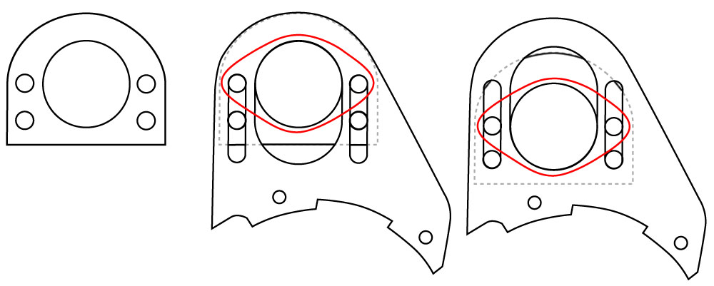
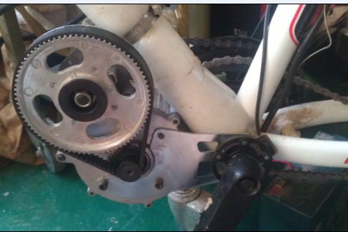
Christerljung I agree that extending the plates is the way to go. I further want mine to be slide adjustable. I'm working up a CAD drawing today. I hope to be able to post this afternoon to show my thoughts. Since my GNG kit is still somewhere in China I used Christer's photos of the sheets to work from. Thanks Christer for posting those!
 
I don't know if this is a possibility, but there is a device called an "eccentric bottom bracket". Its for bikes where there is no derailleur and the rear wheel is not adjustable. By rotating the device, the BB-axle is moved forward or back a couple links of chain. Perhaps something similar could work for the jackshaft? Just an option for thought...

cr0098-390x390.png
 
spinningmagnets said:
I don't know if this is a possibility, but there is a device called an "eccentric bottom bracket". Its for bikes where there is no derailleur and the rear wheel is not adjustable. By rotating the device, the BB-axle is moved forward or back a couple links of chain. Perhaps something similar could work for the jackshaft? Just an option for thought...

cr0098-390x390.png
Dang ! beat me to it :D
 
Here is my idea for making a slide adjustable jackshaft sheet for the GNG. This would allow both the fitting of larger gears or pulleys as well as the proper adjustment of the primary drive side without a tensioner. Since this slides at a right angle to the secondary chain it would have minimal effect on that side. So we'd still need a spring tensioner on that side.

3-4.jpg


3-4_Xploded1.jpg


3-4_Xploded2.jpg


I'm sure that other people will have ideas for making this better. That's what I'm hoping for. I still don't have an actual GNG unit to make cutting paths from but once I do I'll make the paths available to anyone on the forum that wants them. Maybe a few of us can go in together and get a few sets water jetted.

What do you think?

Mike
 
Looks good to me , are the sheets extended to begin with as well as adjustable? ,I think they should be as per Christerljung. If this looks viable ( should probably make a test set ) I'd be in for having them water jetted , if water jetting is not feasable I'll make a set using a plasma cutter or better yet I could use my freinds milling machine.
"D"
 
Yes these are extended. The amount of extension is arbitrary, based on Christerljung's work. Since I don't have my hands on a kit yet I decided to rely on his judgement. They can obviously be extended more if there is a reason.
 
LightningRods said:
Yes these are extended. The amount of extension is arbitrary, based on Christerljung's work. Since I don't have my hands on a kit yet I decided to rely on his judgement. They can obviously be extended more if there is a reason.
My motive here is to have something to trade for help with electronics. I am basically a red to red, black to black kind of electrician. In other words, I'm an idiot about electricity and desperately need help.

I hear ya on the electronics , been looking for a diagram and explanation of components for the controler, I dont know the terminalogy to even do a decent search but give me a hacksaw and a hammer ! :D
 
Amazing what is going on here, maybe we should call this the ES BB dirve thread :D the plates are fine, but I would use retaining washers between the bearing holders and sheets to prevent floating. If this still fails you can go for old-fashioned snake tensioners. This WILL work i am sure.

They have those diagrams for the controller. If the smart guys would just stop arguing over them and agree on what's correct I'd be set!
I guess these controller issues are temporary. Still, can you please post the controller config? What's the argue?
 
If I can break in to the discussion if I may. Have a vintage fat tired bike with a sidecar and I'm using a ezee hub motor with a 36V ezee poly battery and it doesn't have the ability to push the 375 pounds with me on it so I have it on a regular bike.
My question is, will this mid drive have the ability to do the job? Any problems in it's stock form.
Not looking for more that 20 mph and will be using a 123 cell battery with 48V and 20 AH from Cell-Man. This bike is just a fun commuter for a guy near 70 years old.

Your thought and opinion please.

Thank you.
 
Fasteddy, they now have a geared hub motor calling it Gen2 alongside the belt driven.
http://www.gngebike.com/36v350w-48v400w-gen2
edit: just asked about the hub kit weight, complete kit ~6.5kg Jon said. Belt drive kit is under 5kg, ~4.5kg I believe?

Time will tell if "Gen1" belt drive sells out and doesn't reappear.
Notice in one of their photos they have no belt idler, I don't have my kit in hand to compare.
7423489584_066cb0ec26_o.jpg
 
Hi got my GNG 1000W kit last week but had to wait for 4x 6s 5Ah from hobby king. Just got it assembled today. With the help of this forum it was very straight forward. Even for a none bike none electrical person, the only thing I have ever used my multimetre for was to check 15volt power packs were working. I have mounted it on a hard Tail mountian bike. I have a Mongoose Full suspension DH bike but I have to spend money rebuilding that so the hard tail for the moment.

I had two problems. No instructions in my kit when I got it, didn't think I needed them, everything was well labelled. As it turns out you have to join the red Key wire to the battery +. Obvious when you think about it, but not to me I'm afraid. Wavezz2k's post and his photo of his controller wiring solved that one for me. The 2nd one not so easy, The throttle pinouts were reversed. I had 4.3 volts between the throttle red and blue phase wire, had 4.3 volts between red and green on the throttle connector. I then shorted the same and the motor ran. So faulty throttle, looking at the connectors on the controller side it was Green Black Red and throttle side White Black Red. I swapped the White and Red and every thing worked. Went out and tried it out in the empty block across the street, lots of fun :D

It bogged down in heavy sand and struggled on steep piles of earth. I have my 4 lipo pack 12s2p in a back pack. The harness I made up would be 1800mm end to end from lipo to controller. The cable I used I think is only 20Amp. Changed the controller connectors to 30Amp Andersons, have another 4 30Amp Anderson connectors to take the pack from serial to parallel for charging and a couple more 50Amp Andersons about level with the seat to act as a connect disconnect come on/off switch. I got kicked of a few times, twitchy throttle have to get used to that, and the 50Amp Anderon's disconnnected cleanly every time.

The question is would the harness dramaticaly restrict Amperage to the controller. Those skinny little phase wires on the motor side are an issue as well will cut back the length there to about 200mm.

Got to say agian this forum has been a invaluable resouce Thanks agian
 
LightningRods said:
Crossbreak, I was referencing comments by eride and needmorespeed back on page 47 of this thread. They had complaints of surging and low power. Christerlyung tried hooking eride up with a chart http://www24.brinkster.com/lyen/product/controller/Sensored_Combination_Worksheet_V2.htm . From my background in pre-computer era cars and motorcycles this chart seems, um, chaotic. It seems that there are no industry standards for what all of the different hall and sensor wires color codes mean. Is there any standard at all to be able to match up motors and controllers?
I'd just like a photo of the controller opened up with each component named and a description of what it does , me being completely clueless makes it impossible to follow a conversation or understand whats being done to what and why.If there was a book of " motor vehicle electronics for the complete idiot" I'd buy it.
I'm amazed that I havnt found anything helpful in the many hours per day of searching over the past several weeks and when I finally did ask questions I got blown off , Trying to educate myself here folks how bout a little help please.
 
Deepsouth said-
The throttle pinouts were reversed. I had 4.3 volts between the throttle red and blue phase wire, had 4.3 volts between red and green on the throttle connector. I then shorted the same and the motor ran. So faulty throttle, looking at the connectors on the controller side it was Green Black Red and throttle side White Black Red. I swapped the White and Red and every thing worked. Went out and tried it out in the empty block across the street, lots of fun :D
I am also waiting for batteries, in the mean time looking at my throttle wiring plugs I have Red to Green , Black to black and White to red so you are saying this is incorrect and it should be -
Red to red, Back to black and white to green ? The last thing I want to do now is fry something.
Its hell being dumb :oops:
 
Denisesewa Said
Red to red, Back to black and white to green ? The last thing I want to do now is fry something.

Yes thats right, It worked for me. The electronics on these controllers seem to be pretty robust and these are controll lines, but I'm not an authoritive voice. This is Kind of like the blind leading the blind. If you do need to change them this Youtube video show how to pull the pins and put them back on those connectors. http://www.youtube.com/watch?v=kvWYlqMFbGo
 
Oooops ! In my earlier post I wrote "on the controller side it was Green Black Red and throttle side White Black Red" That's what worked.
As it was delivered. On the controller side it was Green Black Red and throttle side Red Black Green. This did not work. I hope that sort of makes sense.
 
bzhwindtalker said:
I got the 219 chain drive working ok and took it for a ride in the snow :)
Got photos? Would love to see some photos of your modifications, bzhwindtalker.
 
Great video, just gave me a reason to take my bike out this winter in the snow. The sliding and drifting looks fun. Good practice as well.
 
LightningRods said:
Here is my idea for making a slide adjustable jackshaft sheet for the GNG. This would allow both the fitting of larger gears or pulleys as well as the proper adjustment of the primary drive side without a tensioner. Since this slides at a right angle to the secondary chain it would have minimal effect on that side. So we'd still need a spring tensioner on that side.
Mike

I would be in for a set, very good idea.

Christer, The noise is quite bad at the moment but I can only improve from that!

Cyclebutt said:
Got photos? Would love to see some photos of your modifications, bzhwindtalker.
I posted a pic on the previous page but it does not show a lot. I used a 80t #25 sproket to make an adapter. I had to cut the aluminium pulley apart to free it from the adaper.
I have a 11-60t ratio, 60t being the smallest 219 sproket available. I used a hand file and the rotating motor to get the axle to the right diameter, then I welded the 11t sprocket on the axle and imediately cooled it.

My mod would be greatly improved with the use of LightningRods's modified plates.
 
bzhwindtalker said:
I got the 219 chain drive working ok and took it for a ride in the snow :)
]

Nice video once again !!
For the final drive how many rear cogs do you use and what sizes are they ? I want to make a 3 speed cassette and would like a starting idea of what cogs to use.
Another week for batteries ARG!!! :(
 
Back
Top