GNG, 1000W 48V BB-drive, $400

skyungjae said:
I've managed to keep my original belt in rather good condition. However, I do pedal quite a bit (usually pedal before giving any throttle), and about half the 300 miles I've put on it is probably downhill with not too much throttle or load on the belt.

I would love to gun it from a stop, but the belt isn't my only concern as is the entire drivetrain shock. It would be quite amazing if I could put 1000 miles on the original belt. :wink:

Regardless, peace of mind is worth a lot, so I do intend on making some changes whenever they're available.

We'll see how long the belt lasts with my 30A shunt mod. :lol:

I have pulling 50a and break a belt every week.
 
LightningRods said:
rp3 said:
Nice work Mike!

Makes me wish I'd waited on the chain conversion now. :cry:

Do you have a timeframe for the tensioners?

The chain conversion is not irreversible. My next phase is a 27mm wide pulley (25mm belt) that will fit on a 12mm motor spindle. This is for the hard core performance freaks. I will be offering new steel motor spindles machined to 12mm diameter.

I was working on the tensioners today. I need to get the exact dimensions of the hardware that I'm going to use for the adjusters. After that it's a week for the laser cutting and another week for zinc electroplating.

Do you have a proto yet?
 
justlooking said:
http://www.ebay.co.uk/itm/221162994...eName=STRK:MEWAX:IT&_trksid=p3984.m1438.l2649

Timing Pulleys HTD5M-25
5mm pitch for 25mm wide belt
Centre drilled or Pilot Bore
in Steel or Aluminium with Zinc plated Steel Flanges

from 12 tooth
to
70 tooth
http://www.ebay.co.uk/itm/HTD-5mm-Pitch-Timing-Pulley-15mm-width-12-72-Tooth-Pilot-bore-CNC-ROBOTICS-/251253993990?pt=UK_BOI_Industrial_Automation_Control_ET&var=&hash=item3a7fe7b206


5m

15mm width

5mm pitch

12 tooth to 70 tooth
 
DrkAngel said:
DrkAngel said:
By my special request ...
Freewheel adapters for the Currie gear reduction motors are now, or very soon, available!
13, 14 an 15T freewheel compatible!
11mm ID w/4mm keyway ... Less than $20!!!

No pictures ... yet.

Also,
Now available,
Adapters for 16T and larger freewheels! ... Less than $20 !

Staton-inc

Ordering up both and will report ... likely ... within a week!

Freewheel adapters for the Currie gear reduction motors are now available!
13, 14 an 15T freewheel compatible!
11mm ID w/4mm keyway ... Less than $20!!!
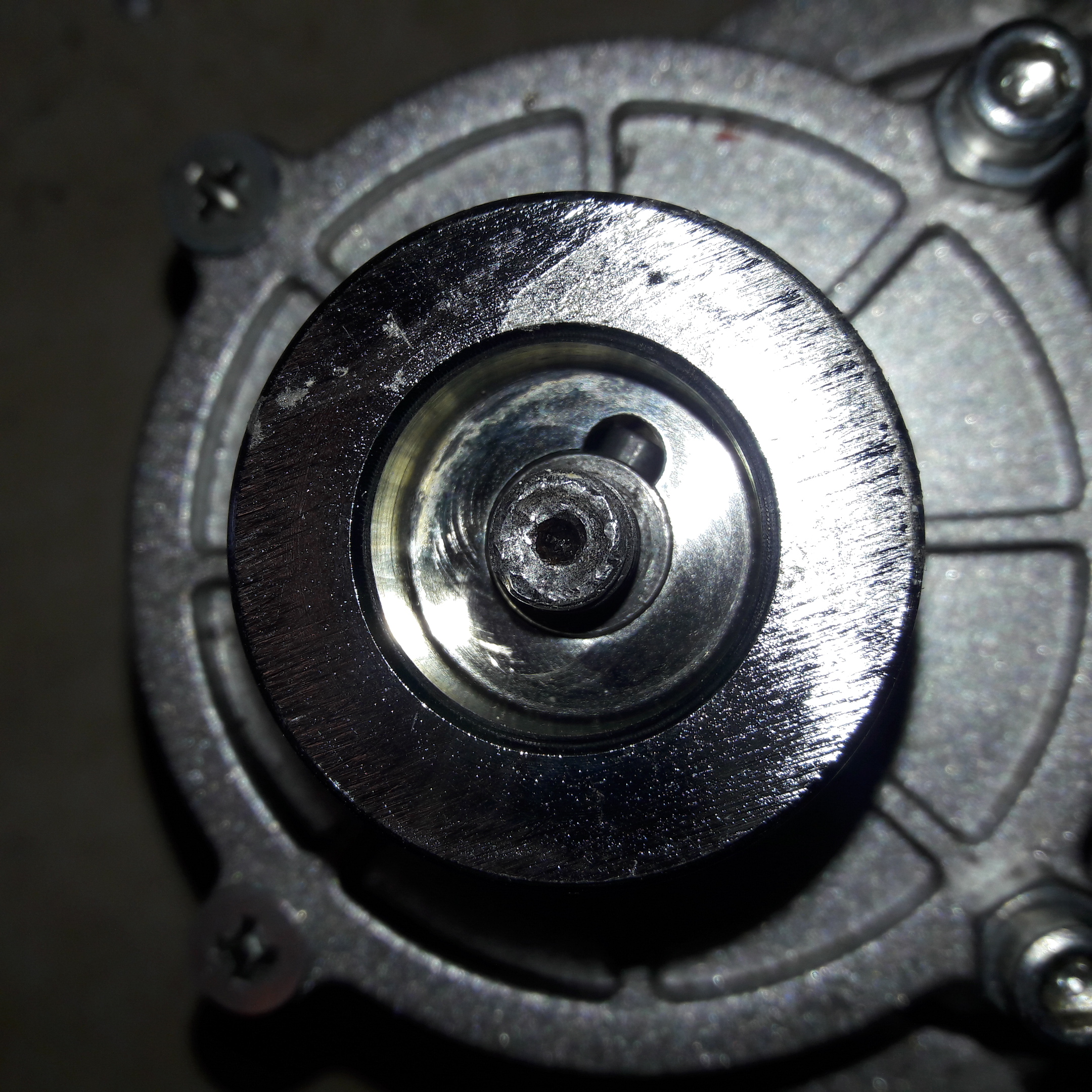
Also,
Now available,
Adapters for 16T and larger freewheels! ... Less than - oops! ... now - $25 !
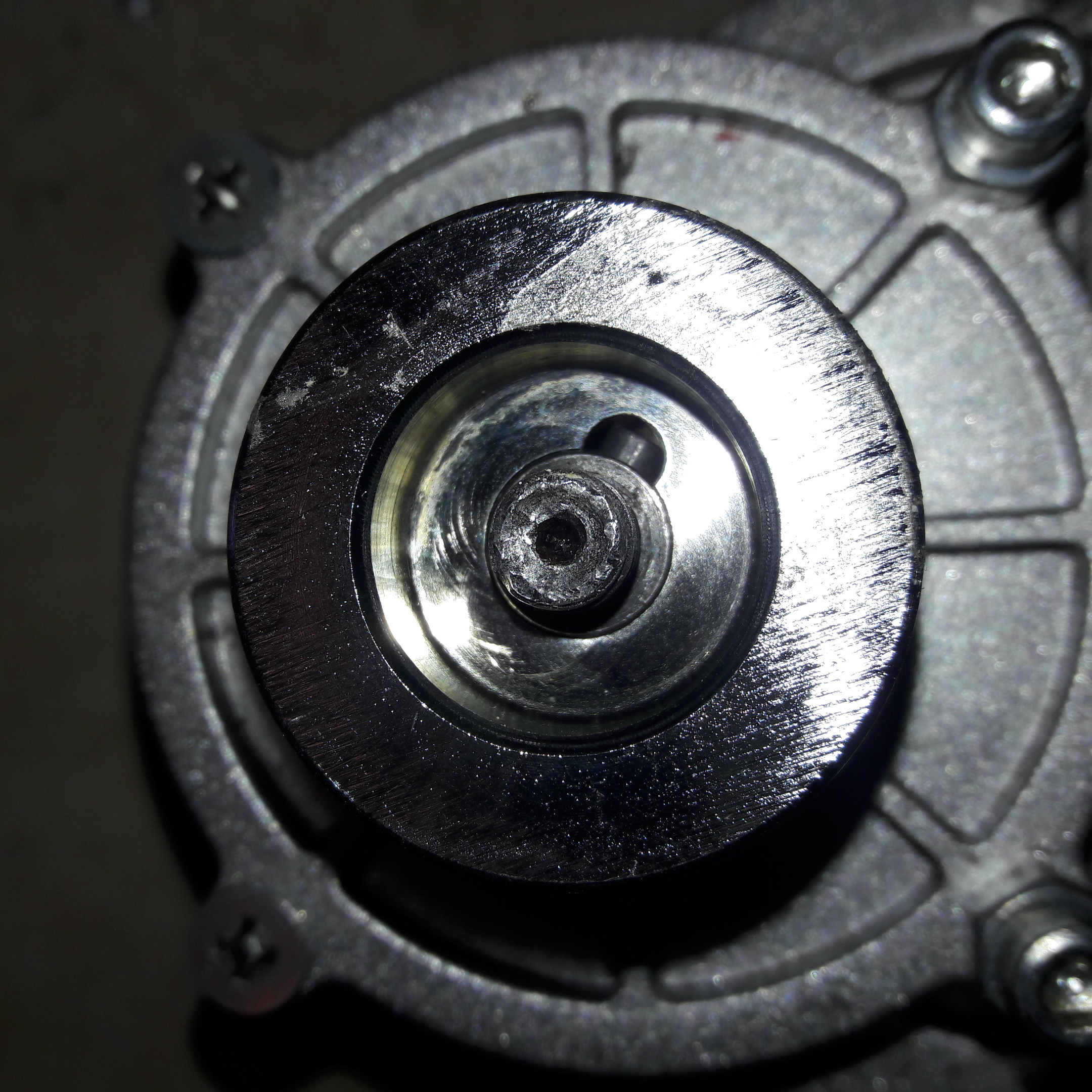
Staton-inc

Ordering up both and will report ... likely ... within a week!

Original Post location (Stronger Freewheel Crankset thread): http://endless-sphere.com/forums/viewtopic.php?f=28&t=47618&start=175#p742892

I feel this information is best suited here rather than in the "Stronger Freewheel Crankset" thread. Though not GNG specific, this is yet another adapter that will allow you to replace your 12T Fanphy jackshaft freewheel if you wish to do so. There is no real issue with that freewheel for the majority of users, but sometimes it's nice to be able to get replacement parts locally much quicker than having to order them from China. It does seem as though more local bike stores are carrying M30x1.0 BMX freewheels. I really like the 13T ACS Crossfire.

IMG_20130531_000008.jpg

From left to right: standard GNG provided Fanphy 12T freewheel; BikeMotive freewheel adapter w/ 13T ACS Crossfire; New ACS Crossfire & Stanton-Inc freewheel adapter.

I haven't had the best luck with the BikeMotive adapter. The original retaining ring that came on the adapter peeled itself off on my first test ride, and the omega style lock ring from Fastenal is being crushed in an uneven fashion causing the freewheel not to spin true under pedaling or motor power. It really wasn't a big deal even when the ACS Crossfire started coming apart. If you look at the photos and compare the new freewheel to the old, there is a gap that causes a lot of play. This is due to the freewheel's outer lock ring unscrewing. One cool thing about the BikeMotive adapter is the weight due to being made from aluminum. It also has holes on the face to use a spanner tool to hold the adapter when needing to remove the freewheel.

IMG_20130531_000020.jpg

IMG_20130531_000036.jpg

IMG_20130531_000412.jpg

IMG_20130531_000432.jpg

BikeMotive v. Stanton, Inc.

The Stanton, Inc. adapter is far more robust than the BikeMotive, but that's because it's steel and has a flange. Fitment was fantastic as well. However, it does weigh in much more and the freewheels will be difficult to remove if they need to be serviced due to not having any tool to help secure the adapter when removing the freewheel. I contacted Stanton, Inc., and they recommended using the keyed shaft to secure the adapter. I think I'll use some tire tube wrapped around a 2x4 and an impact gun. :wink:

As I said before, there's little reason to replace the 12T Fanphy freewheel that comes with the kit, but it's always nice to have other options available.

IMG_20130531_172026.jpg

IMG_20130531_172036.jpg


Personally, I really like the Stanton, Inc. adapter over the BikeMotive mainly due to the cost difference. Also, I'm running 30A+ sometimes hitting 35A, and I feel like the BikeMotive adapter really wasn't meant for a system putting down 1500W. For stock power levels and weight concerns, the BikeMotive adapter is probably the way to go.
 
I lost two cells and am running 10s LiPo know which makes me fight the LVC of the controller ... is there any way to trick the controller to keep running to lower volts or to apply the missing volts somehow without having 20A drown from the "trick-batteries" ?


Thanks!!
 
Secret1511 said:
LightningRods said:
rp3 said:
Nice work Mike!

Makes me wish I'd waited on the chain conversion now. :cry:

Do you have a timeframe for the tensioners?

The chain conversion is not irreversible. My next phase is a 27mm wide pulley (25mm belt) that will fit on a 12mm motor spindle. This is for the hard core performance freaks. I will be offering new steel motor spindles machined to 12mm diameter.

I was working on the tensioners today. I need to get the exact dimensions of the hardware that I'm going to use for the adjusters. After that it's a week for the laser cutting and another week for zinc electroplating.

Do you have a proto yet?

I'm not sure which of the above you're asking about. I have six replacement motor spindles ready to machine to either 10mm or 12mm diameter. I did the CAD work on the upper and lower tensioners and I'm going in to have the first run made tomorrow. Do you want to see the CAD designs?
 
skyungjae said:
Freewheel adapters for the Currie gear reduction motors are now, or very soon, available!
13, 14 an 15T freewheel compatible!
11mm ID w/4mm keyway ... Less than $20!!!

Also,
Now available,
Adapters for 16T and larger freewheels! ... Less than $20 !

It looks very similar in design to the steel 35mm freewheel to 12mm shaft adapter on the stock GNG pulley. It's good to have another source for secondary freewheels other than GNG.

I'm going to cast a 120 tooth driven pulley for the primary side in two different versions. One with integral 12mm bore with square keyway and another with a 3" hole and five bolt pattern to fit either the ACS Crossfire or the White Bros. I'm going to see if the pedaling drag through the jackshaft is an actual problem or just a theoretical problem. For sure being able to fit a larger, stronger and more common freewheel would be good.

The other reason that I want to move the freewheel out of the driver sprocket is that I'm going to experiment with #219 chain on the secondary. I've already purchased a 12 tooth driver, an 80 tooth driven, some good Japanese HD racing kart chain (D.I.D.) and I've designed a freewheel to 5 1/4" kart sprocket adapter. I'm getting it laser cut along with the chain tensioners. If this works as well as I think it will I'll make them available to everyone.
 
So you plan to move the freewheel from the 12 tooth drive sprocket to the crank and use a 219 cart sprocket 80 tooth on a freewheel? Sign me up :mrgreen:
 
dbaker said:
So you plan to move the freewheel from the 12 tooth drive sprocket to the crank and use a 219 cart sprocket 80 tooth on a freewheel? Sign me up :mrgreen:

Yes I do. :D The plan is for 18/120 GT2 belt on the primary side with ACS freewheel and 12/80 #219 HD karting chain on the secondary. 6.66:1 on both sides for a total reduction of 43:1. At 48V the pedaling cadence will be 75 rpm.

You're at the top of my list, Dave. Just as soon as I'm sure it works......
 
LightningRods said:
... I'm going to see if the pedaling drag through the jackshaft is an actual problem or just a theoretical problem. For sure being able to fit a larger, stronger and more common freewheel would be good....

That's the ticket to a much more sophisticated drive. As long as you dont use a silly 14T belt pulley on the left, but much more reasonable 18T, I dont see any more problems. The force on the belt isn't that big that it would induce much friction in the freewheel or the jackshaft bearings.

Why didn't you go for this earlier? Seems that is the solution for all of your problems, if combined with a strong freewheeling crankset ;)
 
crossbreak said:
LightningRods said:
... I'm going to see if the pedaling drag through the jackshaft is an actual problem or just a theoretical problem. For sure being able to fit a larger, stronger and more common freewheel would be good....

That's the ticket to a much more sophisticated drive. As long as you dont use a silly 14T belt pulley on the left, but much more reasonable 18T, I dont see any more problems. The force on the belt isn't that big that it would induce much friction in the freewheel or the jackshaft bearings.

Why didn't you go for this earlier? Seems that is the solution for all of your problems, if combined with a strong freewheeling crankset ;)

LightningRods,

Actually I think your going to see almost identical drag losses if you drop the freewheel as you do when powering through the motor so without your bottom plates and some re-alignment that's about 100-140 watts of loss... I think.

In either case, I can tell you I have tried removing the freewheel from several bb drive systems and "pedaling" into the jackshaft - the losses were always too high for use in real life, it felt like pedaling uphill from a dead stop with every stroke...

Don't let me discourage you though, give it a shot... you seem to work wonders with these GNG drives anyway.

One question though, the newer GNG drives with the enclosed jackshaft - you or someone said it had less loss than the v1.0 design, is that because of the support of the enclose tube? I presume it's the cause of increase because of reduced load from the spacing / assembly hardware in a v 1.0 GNG (which I have 2 of)? I hope that makes sense.

-Mike
 
bee said:
I should be getting my parts soon to do the 117v upgrade. Should I be replacing any of the motors wiring for this? I'll be using Lyen's 12 FET 84-132V High Voltage Racing Controller at around 40-50A
The wiring should be the same as i have on the 12-fet extreme modder controller. It's the first row in the trial and error worksheet diagram supplied by lyen. Don't remember the link, sorry. Chreck with Lyen.
It's just two phase-wires that is different from original setup.
 
crossbreak said:
LightningRods said:
... I'm going to see if the pedaling drag through the jackshaft is an actual problem or just a theoretical problem. For sure being able to fit a larger, stronger and more common freewheel would be good....

That's the ticket to a much more sophisticated drive. As long as you dont use a silly 14T belt pulley on the left, but much more reasonable 18T, I dont see any more problems. The force on the belt isn't that big that it would induce much friction in the freewheel or the jackshaft bearings.

Why didn't you go for this earlier? Seems that is the solution for all of your problems, if combined with a strong freewheeling crankset ;)

Thanks Crossbreak. I am going with 18T. It seems like the sweet spot between engagement and reduction.

I've delayed doing this because of the expense in 3D prototyping a large pulley. There was enough debate about the drag in the jackshaft bearings that I kept putting off rolling the dice. The compromise I finally worked out was to build a prototype that can have either a quality five bolt freewheel center or a 12mm bore. That way users can have a 22mm wide, 120T pulley with or without freewheel. I need an answer to this question of bearing drag and the only way is to try it.
 
mwkeefer said:
LightningRods,

Actually I think your going to see almost identical drag losses if you drop the freewheel as you do when powering through the motor so without your bottom plates and some re-alignment that's about 100-140 watts of loss... I think.

In either case, I can tell you I have tried removing the freewheel from several bb drive systems and "pedaling" into the jackshaft - the losses were always too high for use in real life, it felt like pedaling uphill from a dead stop with every stroke...

Don't let me discourage you though, give it a shot... you seem to work wonders with these GNG drives anyway.

One question though, the newer GNG drives with the enclosed jackshaft - you or someone said it had less loss than the v1.0 design, is that because of the support of the enclose tube? I presume it's the cause of increase because of reduced load from the spacing / assembly hardware in a v 1.0 GNG (which I have 2 of)? I hope that makes sense.

-Mike

Hi Mike-

I'm not clear if your comment about drag pertains to moving the freewheel or removing the freewheel and pedaling back into the motor. I totally agree that pedaling against the resistance of the magnets in the GNG would be miserable. They're powerful and hard to turn by hand. More annoyingly, the resistance 'pulses' as the magnets align. It would drive me crazy. I'd never pedal without at least some power.

My plan is just to move the freewheel from the tiny secondary sprocket to the large primary driven pulley. The only additional drag involved is the bearings in the jackshaft. I can tell you that the bearings in the 1.1 enclosed rotate effortlessly. I turned the jackshaft with my pinky and felt next to no resistance. Additionally, the ACS freewheel is silky smooth and much lower resistance than the gritty, noisy little Fanphy 12T that comes with the GNG. For me the pedaling feel is as important as the drag. I expect a smoother, quieter pedaling experience with just a tiny bit of increased drag. The reliability and easy availability of the ACS seals the deal for me. I'm excited about this experiment. The 18T driver pulley and 120T driven pulley prototypes are at the casting facility now.
 
I got my bike all assembled. I ended up making the battery box out of ABS. Unfortunately, I had my phase wires crossed and cooked something (I have a thread going about that doofus move). Anyway, here's a couple pics of the bike assembled:

wr9P6EL.jpg


X4KcMNM.jpg


9Qcan5C.jpg
 
Nice work, I live the battery box. :D
 
Does anyone know of a good method to identify all of the connectors on the 48v controller? I'd like to find male/female counterparts to connect with. The battery connector and keylock are the most important for me right now. My hope is not having to resort to cutting the existing connectors off.

Edit: My search results look like the controller battery connector is an FM Mobile T-style Connector http://www.qsradio.com/DC-FM-Plug.jpg.

Edit 2: I decided to cut off the T-style battery connector and replaced it with bullet connectors from frys http://www.frys.com/product/4190863. These look much more robust and was already wired with 10awg. They spliced in nice. I don't know the amp rating, but they are definitely working great so far.


4190863.01.prod.jpg
 
rp3 said:
Nice work, I live the battery box. :D

Thanks! It was my first time working with ABS. I really love the stuff now. I built that whole thing with just a hacksaw, sandpaper, acetone, and a hair-dryer I snagged from my wife.
 
can someone post the dimentions of the motor? just diamiter and width, and dia/width of the drive pulley? Im thinking of getting one and building a frame around it, since the motor itself seems like a really solid unit.
 
Is there going to be a Lightningrods full kit available? Like motor, plates, his upgrades, controller? I don't even want to order a GNG kit from china since most of it will be replaced with his parts.
 
spinningmagnets said:
There are some of the specs in the first post/page-1:

Motor is an inrunner about 4-1/2 inches diameter and about 2-1/2 inches wide.

ah shit thanks mate. I looked everywhere, but somehow missed that!! cheers.
 
Back
Top