kartoffelbrei
🧲 New user
i hope this is the correct forum for this question.
i'm was for a strong, open, thru-axle rear hub motor which can fit my yuba mundo v6 bike with two growing kids and loads of cargo on board on a regular basis.
after scanning the market, i came across a supercheap, high-end Go Swissdrive (company closed down a few years ago ) hubdrive which is quite availale here in Germany the only caveat: No controller included, it just comes with bare interfaces,the good side: Should be a great platform for open development, i tought...
my planned setup:
- Lishui contoller (LSW-1216-1-1F) with EBiCS Firmware (master branch) @stancecoke Great to have this!!
- 48 V Battery (13S3P)
- maybe some glue-logic PCB
- a good display (not t hand yet)
The motor provides the rotor position via two quadrature Hall signals, the torque signal via another Hall sensor, and the motor temperature via an NTC resistor; the latter is not of further interest here.
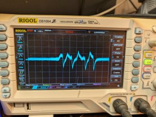
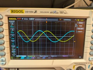
The two analog position signals are output of two Hall sensors (Honeywell SS495A) on a magnetic pole wheel at a rate of 20 sin/cos periods (this is what one would refer to as electrical revolutions ?) per one mechanical revolution.
For this purpose, I have already converted the signals to 3-bit Hall switch signals using a small STM32 microcontroller (Back Pill), some simple filtering is included in order to not get bouncing at edges.
Actually, I’m quite certain that this conversion works correctly; the electrical switching angles are also consistently very similar within successive revolutions, deviating by perhaps +/- 1°
e.g.:
3°
63°
123°
183°
243°
303°
I’ve also already run through these with a small offset (+/-), since i think it's essential to ensure that the magnetic pole wheel runs in sync with the motor’s 20 poles.
The autodetect routine stops after about a 20° rotation, and then the motor continues running at 0.75 U/s.
This rotation sounds like a vintage coffee grinder without beans. It seems to run very inefficient.
(I tested the motor in the exact same mechanical setup — free to move on its axis — as a test using the sensorless_VESC branch; there, it sounds very smooth but doesn’t always run forward.)
Since i feel like i'm starting to get quite desperate about this project not going anywhere...Question for the experts @stancecoke: Since I just can’t seem to find an error in the code, are there any fixed timings or conditions in the firmware that could prevent 20 electrical Hall sequences from being converted into a single mechanical rotation? if there is anything additional information i'd be very happy to provide it.
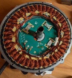
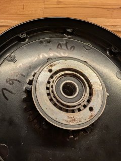
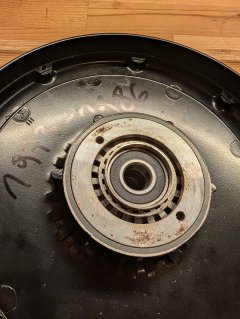
The pics show the interior of the motor, the PCB essentially only holds the three Hall sensors mentioned earlier, two (label HS1 HS2)located center-bottom-right in a line and one (HS3) closer to the center which gives the torque signal(but this is another topic).
i'm was for a strong, open, thru-axle rear hub motor which can fit my yuba mundo v6 bike with two growing kids and loads of cargo on board on a regular basis.
after scanning the market, i came across a supercheap, high-end Go Swissdrive (company closed down a few years ago
) hubdrive which is quite availale here in Germany the only caveat: No controller included, it just comes with bare interfaces,the good side: Should be a great platform for open development, i tought... my planned setup:
- Lishui contoller (LSW-1216-1-1F) with EBiCS Firmware (master branch) @stancecoke Great to have this!!
- 48 V Battery (13S3P)
- maybe some glue-logic PCB
- a good display (not t hand yet)
The motor provides the rotor position via two quadrature Hall signals, the torque signal via another Hall sensor, and the motor temperature via an NTC resistor; the latter is not of further interest here.
The two analog position signals are output of two Hall sensors (Honeywell SS495A) on a magnetic pole wheel at a rate of 20 sin/cos periods (this is what one would refer to as electrical revolutions ?) per one mechanical revolution.
For this purpose, I have already converted the signals to 3-bit Hall switch signals using a small STM32 microcontroller (Back Pill), some simple filtering is included in order to not get bouncing at edges.
Actually, I’m quite certain that this conversion works correctly; the electrical switching angles are also consistently very similar within successive revolutions, deviating by perhaps +/- 1°
e.g.:
3°
63°
123°
183°
243°
303°
I’ve also already run through these with a small offset (+/-), since i think it's essential to ensure that the magnetic pole wheel runs in sync with the motor’s 20 poles.
The autodetect routine stops after about a 20° rotation, and then the motor continues running at 0.75 U/s.
This rotation sounds like a vintage coffee grinder without beans. It seems to run very inefficient.
(I tested the motor in the exact same mechanical setup — free to move on its axis — as a test using the sensorless_VESC branch; there, it sounds very smooth but doesn’t always run forward.)
Since i feel like i'm starting to get quite desperate about this project not going anywhere...Question for the experts @stancecoke: Since I just can’t seem to find an error in the code, are there any fixed timings or conditions in the firmware that could prevent 20 electrical Hall sequences from being converted into a single mechanical rotation? if there is anything additional information i'd be very happy to provide it.
The pics show the interior of the motor, the PCB essentially only holds the three Hall sensors mentioned earlier, two (label HS1 HS2)located center-bottom-right in a line and one (HS3) closer to the center which gives the torque signal(but this is another topic).