
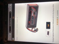
Happy Earth day all. I could really use some advice from the big battery brain brothers and sisters here, about the attached components. Is ‘graphene’ a real improvement in lipo or just a gimmick? It says they only need a ‘normal’ lipo charger, instead of a balancing charger? Can I hook up 5 of these 22.2v batteries together in series to make a 111volt 12Ah battery that would work with the controller and motor here? I believe that would be a 30s 1p battery with 15c? Could I hook up two of of those 5 battery sets together in parallel to make a 30s 2p 111v 24Ah battery? I am still unclear how to find power, in how many watts and amps those batteries can make in relation to these motors and controllers. Could such a battery make anything close to my controllers 800a max., or motors 28kW max.? Would you recommend to hook up only four of these batteries to make a 88.8v battery to prolong life/ minimize trouble overall? Since my scooter has two motors and controllers, is it better to run each motor on its own battery (111v. 12Ah), or both motors on the same (111v. 24Ah) battery? Honestly these seem like a dream come true if they can produce enough power because 10 of them fit right in my scooter and weight only about 40lbs! Also cheaper than the only lithium ion battery I could find that was rated at my motors 12kW rating. Would you recommend a higher c rate battery such as a 45c, 90c max. or higher to build with? Safe to run without BMS if I am SO careful and only charge like Spinning Magnets- 4.1v charge only, 3.6v low voltage cut off, balance charge each battery every ten charges or so and closely monitor? Thank you tons for any help and to all the awesome gurus and builders who are teaching many of us so much. :thumb:
You are using an out of date browser. It may not display this or other websites correctly.
You should upgrade or use an alternative browser.
You should upgrade or use an alternative browser.
Graphene lipo dreams…..?
- Thread starter Scootdan
- Start date

DogDipstick
100 kW
Those Graphene are good cells at a high price per kWh. Like 1000$/ kWh.
To give you an idea, I pay 80$ for a kWh of recycle electric car cells... And they are 2-3x more powerful than the best hobbyking Graphene lipos... But that said...
Graphene from HK will fly a plane very fast. Yes some use huge HK lipo banks.
To give you an idea, I pay 80$ for a kWh of recycle electric car cells... And they are 2-3x more powerful than the best hobbyking Graphene lipos... But that said...
Graphene from HK will fly a plane very fast. Yes some use huge HK lipo banks.
DanGT86
100 kW
The hobby battery market is full of ambitious ratings. When they say the cells will peak at 30c (12A x 30c=360 amps) I think they mean without exploding.
Some hobby lipo packs experience pretty bad voltage sag above 5-6c. I believe the graphene ones are better than the standard ones but I would not expect a true 360amps out of these for any useful amount of time. Not to mention if you are using them like this then you are looking at 2min of run time. Most of the time people just end up with a larger capacity pack on high powered vehicles because they want to use them for things other than racing.
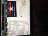
If you are really looking for extremely power dense cells for short bursts like racing you should take a look at these. John Metric has broken plenty of records with these cells. This is about the most extreme end of the spectrum for power density.
https://www.lonestarevperformance.com/sleeper-cells.html
You could buy the HK graphene cells and try them because you could relatively easily add more of them in parallel. Just don't blow your entire budget on a pack you expect to run at 30c. You will probably be disappointed. I like to plan around 3-5c avg and occasionally burst to 10c for very short bursts.
As for multiple controllers and motors I would hook them to the same battery. You don't want to deal with 2 batteries discharging at different rates.
Some hobby lipo packs experience pretty bad voltage sag above 5-6c. I believe the graphene ones are better than the standard ones but I would not expect a true 360amps out of these for any useful amount of time. Not to mention if you are using them like this then you are looking at 2min of run time. Most of the time people just end up with a larger capacity pack on high powered vehicles because they want to use them for things other than racing.
If you are really looking for extremely power dense cells for short bursts like racing you should take a look at these. John Metric has broken plenty of records with these cells. This is about the most extreme end of the spectrum for power density.
https://www.lonestarevperformance.com/sleeper-cells.html
You could buy the HK graphene cells and try them because you could relatively easily add more of them in parallel. Just don't blow your entire budget on a pack you expect to run at 30c. You will probably be disappointed. I like to plan around 3-5c avg and occasionally burst to 10c for very short bursts.
As for multiple controllers and motors I would hook them to the same battery. You don't want to deal with 2 batteries discharging at different rates.
j bjork
1 MW
I dont think 30s makes sense if 118v is max for the controller, that is just 3,93v/cell.
I think 28s would be perfect, 117,6v if you charge all the way to 4,2v/cell. Or 116,2 at 4,15v/cell.
If you want to push it 29s would be slightly under 4,07v/cell at 118v and would be good for long life of the cells.
(more interesting for a daily driver than something that gets used once a week)
You need very powerful cells for your 2x300A controllers on a small vehicle.
If you end up with a 20Ah battery it have to deliver 30c for 600A.
That would probably mean some of the toughest rc lipos with a 60c rating or so, but others are probably better suited for recommendations.
Edit. I didnt see DanGT:s post before posting.
A normal RC Lipo charger *is* a balancing charger.Scootdan said:It says they only need a ‘normal’ lipo charger, instead of a balancing charger?
To charge using RC LiPo chargers, with a "walk-away" setup, you would need as many of those chargers as you have packs in series, and they would need to be "isolated", meaning the outputs of the chargers must not connect to their inputs (you can test that with continuity or ohms on a multimeter, while chargers are not connected to battery or wall or each other).
With only one charger, you can charge only as many cells in series as the charger is designed for usually six). So you would charge one pack, then the next, then the next, then the next, manually moving the charger connections each time.
Either method would require disconnecting the packs from each ohter and the scooter, or creating a wiring harness that provides a connection for charging at the main leads of each pack, plus it's connection to the ohter packs and the bike.
You can certainly hook them up, but you cannot fully charge the pack, or it will probably damage the controller. Fully charged at 4.2v, the cells would be 4.2v * 30s = 126v, and the max controller voltage is 118v. If they are rating it near the component maxes (pretty common), it'll probably fail either at first turn on or during early usage.Can I hook up 5 of these 22.2v batteries together in series to make a 111volt 12Ah battery that would work with th`controller and motor here?
If you are running right at the edge of the controller's voltage limits (but still below them), you also run the risk of damaging it using regen, or even just from random voltage spikes. Depends on the controller hardware and software design, which you'd have to reverse engineer to find out if it's well-designed for such situations or not.
") I would personally rather assume it's not well-designed in this regard, as that is more typical than not, even for expensive controllers.
I would personally rather assume it's not well-designed in this regard, as that is more typical than not, even for expensive controllers. If you don't fully charge the pack, you don't get it's full capacity, so you don't get the full range you could from it. More on that later.
I wouldn't base the build on the marketing division's idea of cell ratings. It's likely that there will be significant voltage sag at medium to high C-rates, as well as cell heating. If your system is expected to run at high currents for long periods, it may degrade the cells more quickly than you would like, leading to a short lifespan for the cells (this doesn't matter much for RC applications, and it is generally even expected).I believe that would be a 30s 1p battery with 15c?
Additionally, you get less capacity out of a pack the higher the rate you pull the current out. Think of it like pouring water from one thing to another--if you pour it at a slower rate there's less splatter outside the destination, so more of the water makes it into the destination, but do it too fast and more of it splaters and is lost. This chart for a different cell is an example:
https://lygte-info.dk/review/batteries2012/Samsung%20INR18650-25R%202500mAh%20%28Green%29%20UK.html
![Samsung%2520INR18650-25R%25202500mAh%2520(Green)-Capacity[1][1].png](https://endless-sphere.com/sphere/data/attachments/179/179654-1ea10d36115a18fb05767b622b90d984.jpg "Samsung%2520INR18650-25R%25202500mAh%2520(Green)-Capacity[1][1].png")
More on that later.
You can, if you build your wiring harness to do so. If it is used at the same current draw (amps) as the 1p pack would, it would be half as hard on the cells as a 2p pack than a 1p pack. If used at twice teh current draw, it's the same as having the 1p pack at the lower rate.Could I hook up two of of those 5 battery sets together in parallel to make a 30s 2p 111v 24Ah battery?
Watts = Volts x Amps.I am still unclear how to find power, in how many watts and amps those batteries can make in relation to these motors and controllers. Could such a battery make anything close to my controllers 800a max., or motors 28kW max.?
Volts is the average voltage of the packs, assuming 3.7v / cell x number of cells in series.
A 30s pack would be 3.7v x 30s, or 111v.
Amps max (peak) is the max peak amps of the controller's battery current limit. (if it has a phase current limit, that applies only to the motor side). If you are not using the system at it's limits (turned down the current limit in software, or simply never loading it enough to reach them), then the Amps max (peak) is whatever you measure during peak loads. If there is more than one controller, it's the total of both if connected to the same battery.
Amps continuous is the continuous current you measure during use, at the battery output to the controller(s). If you don't have a working system to measure from, you can use the http://ebikes.ca/tools/simulator.html to get an idea of how much current it will take to do the specific job you want it to do under the specific conditions you want to do that job under. For your power levels you'll need to use the "custom" option in the dropdowns for motor, controller, and battery, to input your own numbers, to get realistically useful graphs.
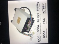
Looks like those are not 800A controllers. They are 100A controllers. The 300A is probably a peak for a few seconds, but they don't actually specify what it means. So assume only 100A max continuous current before they explode.
Let's assume you draw 100A per controller continously and as a max peak current, so all the time for a whole ride, or 200A total.
Let's assume the cells have zero voltage drop (not going to happen) at their max C-rate, so 15C x 12Ah = 180A.
To supply that, you would have to have at least a 2p pack of those cells, and they would be running up towards their max C-rate to do it. While doing this, cell heating will increase, degrading the cells faster than normal, and increasing their internal resistance which increases the heat....
If the controllers really can draw 300A each continuously, then you have a 600A setup, and to get that you'd need a 4p pack, assuming usage at the max continuous C-rate of the cells.
Also, the actual capacity you get will be less at the higher rate, probably by a significant amount. Let's say you only get 10Ah instead of 12, just because of the rate you draw the power out. Let's also say you're not fully charging the packs so that they won't blow up the controllers, so you also lose a couple Ah from that, you only get 8Ah. Let's also say you're not fully discharging hte packs so you don't wear them out as quick, so you lose another couple Ah from that. Then you only get 6Ah, or only half what the packs can supply. So to get 12Ah you need a 2p pack for that reason, too.
Let's say you are actually drawing 200A from the 24Ah 2p pack. 24Ah / 200A = 0.12 hours, or 7.2 minutes runtime maximum. But since you really only have, say, 12Ah usable you only get 3.6 minutes maximum actual runtime.
Motor watts only applies to the controller output; then the controller itself applies to the battery output. Meaning, you must have a motor that can handle the amount of power needed to do the job you need it to do under worst case conditions for as long as those conditions exist, as often as they come up. Then you must have a controller that can supply *at least* that amount of power. Then you must have a battery that can supply *at least* that amount of power, plus an amount to account for the losses from the efficiency of the controller.
It is best if the battery is used at a C-rate that has the least amount of voltage sag, to maximize the volts you get out of it at it's highest amp loading, which then maximizes the watts you get out of the system.
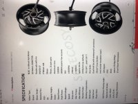
Yes, but: The voltage of the system, and (for hubmotors in a wheel) the winding of the motors (their k/V or RPM/Volt), vs the diameter of the wheels/tires, determines the maximum unloaded speed you get out of the system. You have to setup all of those things together to ensure that (assuming your system has the power needed to overcome air resistance at that speed) you can go the speed you want.Would you recommend to hook up only four of these batteries to make a 88.8v battery to prolong life/ minimize trouble overall?
Many (most?) hobby / DIY components (rather than parts supplied only to large OEMs) will be "rated" with fairly extreme numbers (rather than conservative numbers that won't stress the components), so using them below those "rated" abilities will increase it's lifespan *and* it's performance.
For redundancy in case of failure, or if the current required is enough to cause significant voltage drop on wiring from battery to controller with the max wiring size you can use on the available connections, and the batteries can be placed very close to the controller/motor if they are separately powered, then separate packs makes sense. Otherwise, it doesn't really matter. The load on the packs would be the same, assuming the load on each motor is the same and each motor/controller is identical and used identically.Since my scooter has two motors and controllers, is it better to run each motor on its own battery (111v. 12Ah), or both motors on the same (111v. 24Ah) battery?
There isn't really such a battery that I'm aware of; just marketing deciding to call them that. This is as common with RC LiPo cells as it is for toolpacks to use their max full charge voltage as the rated voltage (when everyone else uses the average voltage), among other market-specific battery marketing-speak that causes confusion.Honestly these seem like a dream come true if they can produce enough power because 10 of them fit right in my scooter and weight only about 40lbs! Also cheaper than the only lithium ion battery I could find that was rated at my motors 12kW rating. Would you recommend a higher c rate battery such as a 45c, 90c max. or higher to build with?
Note that if a battery is cheaper, but is marketed as more capable than another, there is either another serious drawback to that cheaper battery, or it is not actually any more capable (likely is less!) than the other battery.
How will you know that any specific cell has reached 3.6v? Are you going to use individual-cell voltage alarms? If not, then a BMS that at least monitors them and can notify you in an unmistakeable way that a cell has dropped below your specified limit is a good idea. (even if it doesn't shut off output or otherwise shutdown the system).Safe to run without BMS if I am SO careful and only charge like Spinning Magnets- 4.1v charge only, 3.6v low voltage cut off,
If you don't monitor, live during a ride, then you cannot know when a cell has dropped below your limit (or is at any particular voltage at all), and cant' know anything about the health of the cells, since they wont' experience anything like the loading / currents your system will apply during any other testing you can do, unless you build a test setup just to do that, which probably wont' be simple.
scianiac
10 kW
- Joined
- Oct 24, 2018
- Messages
- 644
There are many pros and cons to prismatic hobby cells vs cylindrical cells vs prismatic industrial cells. The hobby cells can output extremely high power levels at the cost of poor energy density and life cycle (although the life cycle is still pretty good if you consider miles ridden per $ so I wouldn't worry too much about it).
The thing I would say is while hobbyking stuff used to be pretty great, it seems to have fallen behind now and I wouldn't be buying any of their high end stuff (although I have been running a few of their "zippy" packs in quadcopters (so pretty high discharge) and they've held up great in spite of their low price) since it seems to perform rather mediocrely compared to much more cost effective offerings from manufactures like GNB and CNHL which seems to stack up pretty good in most of the battery tests I've seen and are generally much cheaper than the high end hobby king stuff.
In the end the advertised numbers are pretty much worthless and if you are going to be using cells at high power ratings (which honestly only happens if you have a lot of power and a small battery pack) you should find some actual tests where you can compare discharge curves at the current you will be asking of them. And you can compare those tests of hobby prismatic cells to high discharge cylindrical cells like the tests from lygte or mooch.
Edit: One more thought, you probably should figure out just how much battery you're going to have because that's probably the most important part of the puzzle. Some of these high performance cells are designed to be discharged in like 2-3 min. And while you may want that much power for short bursts you still want a big enough battery to have reasonable range which means more reasonable discharge rate cells either prismatic or cylindrical generally are more suited for most applications because they have higher energy density. Bigger battery, same current, lower discharge cells.
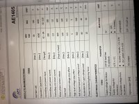
Thank you guys so much. Learning from all of you experts with years and years of experience is so very awesome! I have started reading about the recycled EV cells Mr. Dog, and I love the price and construction of many of those. For this project I think lipo is more what I would be after . I really appreciate the link Mr. DanGT. I will definitely be looking into those, although I am very fearful of their price! I really appreciate your advice on the c rate brother. Thank you also to Mr. j bjork for helping me understand this stuff a little! I am attaching the specs they sent with my controllers to show you and Mrs Amberwolf that they say they can handle 120-140volt max battery voltage. That is the only reason I would go for a 111v over 88.8v battery, I think it could handle it. Man I am loving your builds also brother j bjork very clean and fun looking! And Mrs Amberwolf, I owe you a favor ma’am. I so appreciate how you help me so much. You are an invaluable resource here and have helped so many of us it is amazing. All this information is really helping me to zero in on what battery will work best. I will respond more later, but just wanted to quickly post these specs. and tell all you guys again, thank you, thank you, thank you.
Attachments
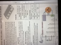
In case you didn't notice, that's a COMPLETELY different controller than the one you posted previously, so it's not surprising it has different specifications. (they don't even remotely resemble each other visually)
If the place you're buying from has the ad showing one of them but they send you info about the other one, you should buy from a different place, because you can't trust what they will actually be sending you--it could be yet another completely different controller.
(comparison below of the two, using the original images)
![3A323092-26CE-4ED0-BBB5-AA8BBF577949[1].jpeg](https://endless-sphere.com/sphere/data/attachments/179/179661-2ba623547b28e8b4b26f443557e2508f.jpg "3A323092-26CE-4ED0-BBB5-AA8BBF577949[1].jpeg")
![8B724A54-5F78-4C60-AC6C-22F46A5FE755[1].jpeg](https://endless-sphere.com/sphere/data/attachments/179/179663-bfbb51cbad8196c36521781088cf6869.jpg "8B724A54-5F78-4C60-AC6C-22F46A5FE755[1].jpeg")
![07C429CE-85CE-4C46-80B1-04001D77A8D5[1].jpeg](https://endless-sphere.com/sphere/data/attachments/179/179664-e311b56eaf077b42afccf54e6de54b16.jpg "07C429CE-85CE-4C46-80B1-04001D77A8D5[1].jpeg")
![F6EFBF40-34BE-4B2D-82EE-8BFB018C848F[1].jpeg](https://endless-sphere.com/sphere/data/attachments/179/179662-364929aabead9e3f705e2d58268da04f.jpg "F6EFBF40-34BE-4B2D-82EE-8BFB018C848F[1].jpeg")
(they don't even remotely resemble each other visually)If the place you're buying from has the ad showing one of them but they send you info about the other one, you should buy from a different place, because you can't trust what they will actually be sending you--it could be yet another completely different controller.
(comparison below of the two, using the original images)
I know it looks suspicious, but there is a reason they are different Mrs Amberwolf. They are both APT controllers, one is their 96600 - and mine is their 96800. The 96600 is for 96v 600a peak and the 96800 is 96v 800a peak. The 96800 doesn’t even have its own ‘Manuel’ . They only give you the one for the 96600, because they share many features and interfaces. You can see actual specs for both controllers in the data here. Bottom line for me is I feel comfortable ( for a newbie) that the 96800s should be ok to handle 118v > fully charged voltage, wouldn’t you think? My plan was the motors and controllers would not be the weak links, and I could start small and safe with the battery until I can really feel how much power my battery gives. Then I should get the best sense of what battery I really need, and what I really can have or get. Hopefully this is all just till brother Luke can sell me a couple of his 2400A controllers for my next scooter! Haha! That would need a serious battery. Thank you again ma’am. :thumb:
liveforphysics
100 TW
I would go with multiples of smaller high C rate pouches personally. The bigger cells tend to fuse there own tabs and/or melt the solder joints too easily in applications that can draw continous high power.
Thank you very much Mr Luke. I was just looking at Dr. Bass’s 15 Zippy battery pack and that looks nice. Are those considered smaller pouches? Or are Zippy type batteries still cells that are soldered, and pouches are like these sleeper cells? Dr. Bass is off the creativity charts by the way. I am getting really excited about this much power this light and small! I am really honored to learn from and get help from such super gurus as you, dr. Bass, amberwolf, Mr. Chalo, mr. spinning magnets, and on and on. And some of these builds are just fantastic. Totally electrifying! 8) Man I think we are all waiting to see the next Deathbike though Luke. You are truly amazing brother. Thank you guys again for all the help.
Attachments
DanGT86
100 kW
I believe Dr. bass was experimenting with some lonestar cells a few years ago on a race bike application. If I recall they used to be sold as 5ah pouches. Looks like they are 20ah now but the tabs look pretty big.
I like how John Metric (lonestar) used to extensively datalog his 1/4 mile passes so you can get real life examples of the cells performance under huge load.
He's also not trying to make a living selling batteries. He sought out tech that worked for him racing and then offers it to the community on an as needed basis. I trust him and his specs more than someone exclusively in the battery selling business.
DogDipstick
100 kW
DanGT86 said:I trust him and his specs more than someone exclusively in the battery selling business.
I do not.
Quite the opposite, actually.
I'll never trust someones own numbers.. first off.. and well... yeah, I'll stop talking trash bout other enthusiast's products right there... for now.... yeah.
I trust independent testing by skilled electrical engineer hobbyists.
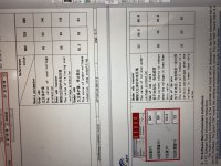
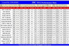
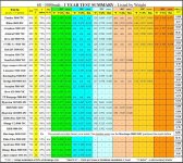
Anyway, here are some testing summary of commonly available consumer grade lithium polymert cells. I have a few machines here that are built specifically to hit these cells as hard as the manufacturer can support. Zippy are kinda the worst. I can puff a Zippy in a day... Those Graphene hit hard.
THere is probably a new report out by now over @ RC Groups. I'll look.
Attachments
-
 35C Results by LPB.jpg333.9 KB · Views: 516
 -
 1yeeere.JPG196.4 KB · Views: 516
 -
 Consumer Report 062321.jpg546.2 KB · Views: 511
 -
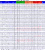 All 2021 LPB Results.Jpg509.9 KB · Views: 511
 -
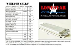 Lonestar_EV_Performance_Sleeper_Cell_datasheet_200C2-600x386.jpg47.7 KB · Views: 506
 -
 All 6000+ 2021 EDensity Results.Jpg605.1 KB · Views: 506
DanGT86
100 kW
DogDipstick said:DanGT86 said:I trust him and his specs more than someone exclusively in the battery selling business.
I do not.
Quite the opposite, actually.
I'll never trust someones own numbers.. first off.. and well... yeah, I'll stop talking trash bout other enthusiast's products right there... for now.... yeah.
I trust independent testing by skilled electrical engineer hobbyists.
Independent tests are best for sure.
I guess what I was trying to say more specifically is that the guy behind those lonestar cells was very transparent about his build. Lots of specifics about the battery pack covered in forum posts as the project came together. He has the documented record breaking cars to back it up.
So if you know how many cells are in the pack and you know the confirmed ET and weight then there is not much room for speculation.
Those runs and datalogs make me feel better than hobbyking's spec sheets.
Also, thanks for the spec sheets! Thats a lot of good info. That should be in a reference section on the forum somewhere.
liveforphysics
100 TW
We have 2,000Amp DC loads for doing discharge tests. I have some of the higher C rate pouches to test. Just need to have a pause in urgent client work and I can share data.
jimmyhackers
10 kW
- Joined
- May 11, 2015
- Messages
- 609
as said. take C ratings with a pinch of salt.
most advertised are peak C rating rather than continuous C rating. make sure you know both and stay below them.
its like your cars speedo might go upto 200mph.....but your car wont last long if you're doing 200mph all the time.
there is a lot of "fudging the statistics" in the battery marketing world.
like "burst" is such a open ended term. how long is a burst?....how often can i burst?... a proper rating would be "burst X C for Y seconds with a X duty cycle percentage.
you are supposed to calculate discharge current by multiplying the C rating by the overall Ah capacity of the battery.
i prefer to use the remaining Ah capacity, but i feel the truth lies somewhere between the two.
i like a discharge rate of 1C or as close to as possible, avoids a lot of headaches.
liveforphysics
100 TW
Ive tested cells that will do 60C continous discharge (1minute to drain) from start to finish without going over 50degC. The 1-2Ah range drone racing packs did best a few years ago. I'm looking forward to testing more recent performance cells when I get time available.
To be ideal for drag it should be about 180C continuous, 300C rate burst (a few seconds).
To be ideal for drag it should be about 180C continuous, 300C rate burst (a few seconds).
jimmyhackers
10 kW
- Joined
- May 11, 2015
- Messages
- 609
1 minute to discharge, flippin eck!
thats mad, if you set a battery on fire it would probably take longer to "deplete" :lol:
thats mad, if you set a battery on fire it would probably take longer to "deplete" :lol:
Similar threads
- Replies
- 8
- Views
- 2,039
- Replies
- 1
- Views
- 283
- Replies
- 4
- Views
- 931
- Replies
- 7
- Views
- 1,254