CGameProgrammer
10 kW
I'm an electronics newbie who tends to make fatal mistakes both real and theoretical, so I wanted the simplest method possible for adapting DeWalt 36V 2.3Ah battery packs for use in an e-bike.
The thing that is mandatory to change is the charging mechanism. Normally you have to take an individual battery and insert it directly into the charger; there's no cord. This is impossible to do when you have multiple batteries in series/parallel; you don't want to have to disconnect and remove each battery every time you need to recharge your e-bike.
There are three solutions:
1) Remove the BMS from each battery and attach one BMS to the charger, then use your own connectors to connect the BMS back to the battery for charging.
The advantage of this is you have full control over the connectors used, but the disadvantages are that you'd have to modify every single battery you use and this is pretty time-consuming. Besides, there would be 15 wires you'd need to connect, and wiring up a 15-pin connector for every battery would not be enjoyable.
2) Remove the connector from the charger and plug it into a battery basically forever, using your own connectors to connect that back to the charger.
This requires no modifications at all to the batteries, but you would need one charger for every battery to make it practical.
3) Remove the connector from the charger and extend the wires that go from the charger to it.
This is the solution I've chosen and will be detailing here. It's very easy to do and requires no modifications to the batteries themselves. The disadvantage compared to option #2 is that this connector still has to be plugged directly into the batteries, so you would need to make sure every battery you use is easily accessible on your vehicle.
First we need to remove the yellow cover from the charger. It is easily removed by unscrewing six screws on the bottom with a "tamper-proof" Torx T-15 bit:
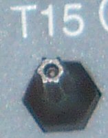
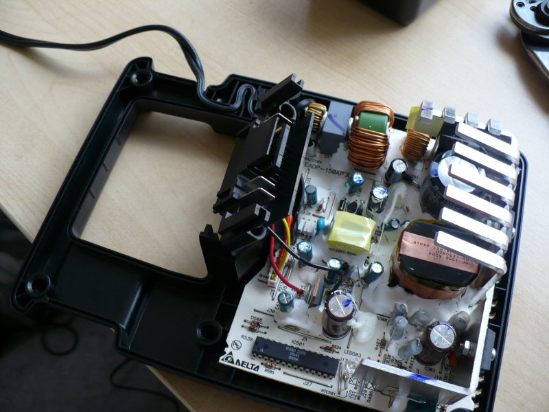
...not to be confused with the Torx T-10 that's needed for the battery's screws. Remove the cover and look at the connector in the middle. It turns out it's a completely separate piece of plastic that isn't even held down at all anymore! Here it is slightly lifted up and at an angle (the wires are quite short so it can't be moved much):
Cut those wires. There are eight. We'll be splicing wire inbetween so try to leave enough length on each side to make the task easy.
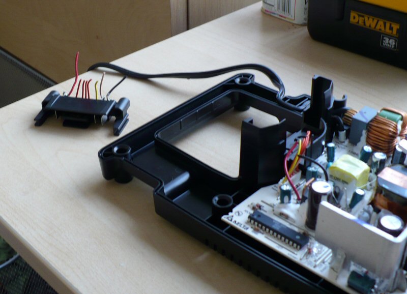
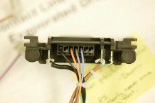
See? There's the connector removed from the charger. All I did was cut eight tiny wires and it's off.
The positive and ground wires appear to be 18-gauge, and the balancing signal wires are all around 22-gauge, possibly smaller. But I just used 20-gauge wire to connect everything. I cut all my wire to a generous five feet long so I could charge any battery anywhere on the bike without having to move the charger around. So... start splicing!
First wire soldered:
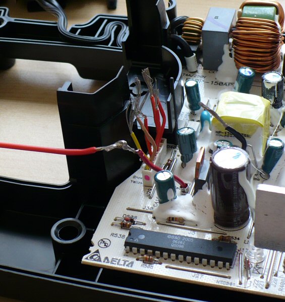
All eight soldered and wrapped:
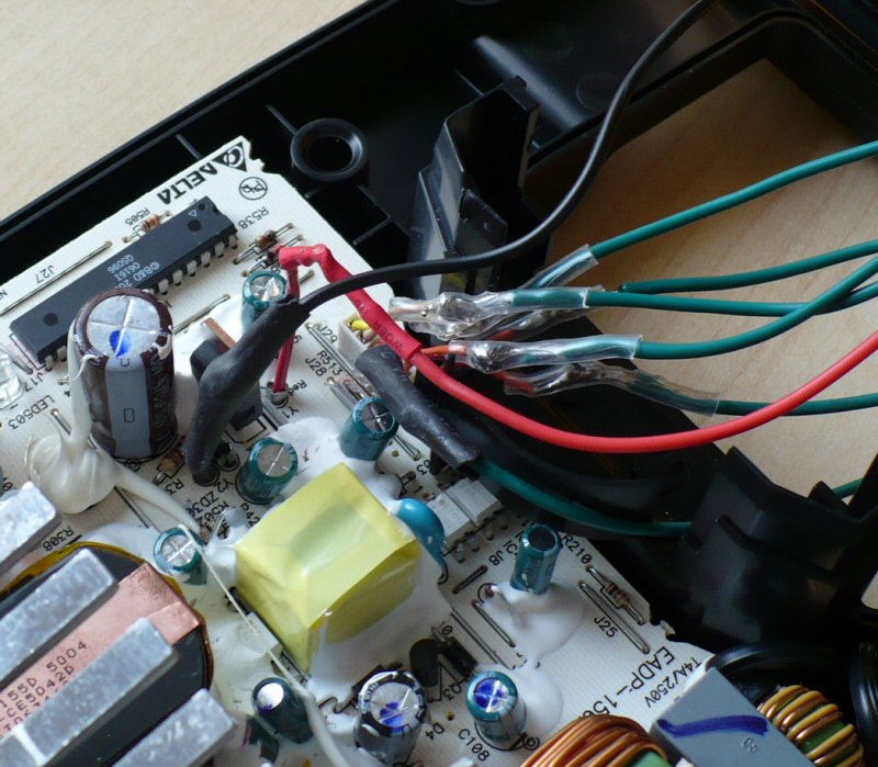
Now if you didn't use a unique color for each wire then you should label them now so you can know which is which later. Then screw the yellow cover back on. There's room enough for the wires to escape through the bottom of the area where the connector used to be:
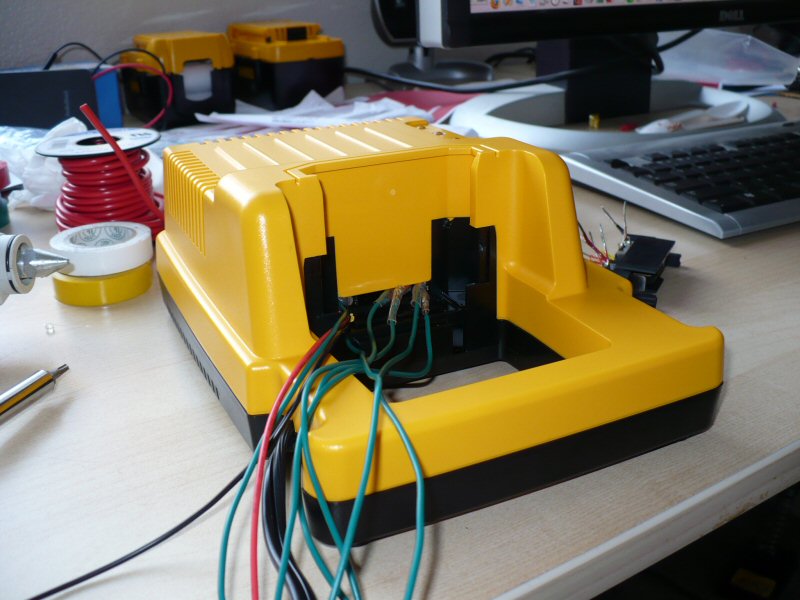
Now you should separate the wires into two groups and braid them around each other like a double-helix. This keeps them neat but flexible. You can also just use a wrap if you want, or tons of tape. Once that's done, attach the wires to the connector.
Because we're now exposing those contacts to physical stress and environmental hazards that it never was designed to deal with, I suggest using a hot-melt glue gun to drench the wires on both ends, both insulating them as well as making a good physical connection that can intercept stress otherwise placed on the solder joints themselves.
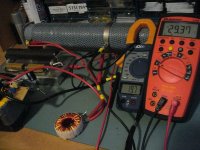
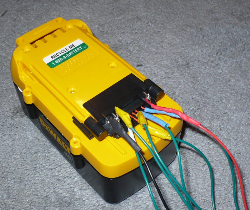
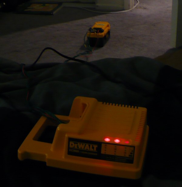
Now plug the connector into a battery and charge it! It goes like this (the entire black thing is the connector):
It's alive!
Done! Not too bad. Getting additional chargers and making the same modifications should be a fairly quick procedure, but you only really need one anyway.
(edit: replaced broken image links)
The thing that is mandatory to change is the charging mechanism. Normally you have to take an individual battery and insert it directly into the charger; there's no cord. This is impossible to do when you have multiple batteries in series/parallel; you don't want to have to disconnect and remove each battery every time you need to recharge your e-bike.
There are three solutions:
1) Remove the BMS from each battery and attach one BMS to the charger, then use your own connectors to connect the BMS back to the battery for charging.
The advantage of this is you have full control over the connectors used, but the disadvantages are that you'd have to modify every single battery you use and this is pretty time-consuming. Besides, there would be 15 wires you'd need to connect, and wiring up a 15-pin connector for every battery would not be enjoyable.
2) Remove the connector from the charger and plug it into a battery basically forever, using your own connectors to connect that back to the charger.
This requires no modifications at all to the batteries, but you would need one charger for every battery to make it practical.
3) Remove the connector from the charger and extend the wires that go from the charger to it.
This is the solution I've chosen and will be detailing here. It's very easy to do and requires no modifications to the batteries themselves. The disadvantage compared to option #2 is that this connector still has to be plugged directly into the batteries, so you would need to make sure every battery you use is easily accessible on your vehicle.
First we need to remove the yellow cover from the charger. It is easily removed by unscrewing six screws on the bottom with a "tamper-proof" Torx T-15 bit:
...not to be confused with the Torx T-10 that's needed for the battery's screws. Remove the cover and look at the connector in the middle. It turns out it's a completely separate piece of plastic that isn't even held down at all anymore! Here it is slightly lifted up and at an angle (the wires are quite short so it can't be moved much):
Cut those wires. There are eight. We'll be splicing wire inbetween so try to leave enough length on each side to make the task easy.
See? There's the connector removed from the charger. All I did was cut eight tiny wires and it's off.
The positive and ground wires appear to be 18-gauge, and the balancing signal wires are all around 22-gauge, possibly smaller. But I just used 20-gauge wire to connect everything. I cut all my wire to a generous five feet long so I could charge any battery anywhere on the bike without having to move the charger around. So... start splicing!
First wire soldered:
All eight soldered and wrapped:
Now if you didn't use a unique color for each wire then you should label them now so you can know which is which later. Then screw the yellow cover back on. There's room enough for the wires to escape through the bottom of the area where the connector used to be:
Now you should separate the wires into two groups and braid them around each other like a double-helix. This keeps them neat but flexible. You can also just use a wrap if you want, or tons of tape. Once that's done, attach the wires to the connector.
Because we're now exposing those contacts to physical stress and environmental hazards that it never was designed to deal with, I suggest using a hot-melt glue gun to drench the wires on both ends, both insulating them as well as making a good physical connection that can intercept stress otherwise placed on the solder joints themselves.
Now plug the connector into a battery and charge it! It goes like this (the entire black thing is the connector):
It's alive!
Done! Not too bad. Getting additional chargers and making the same modifications should be a fairly quick procedure, but you only really need one anyway.
(edit: replaced broken image links)