Hall effect troubleshooting

dick slessig

100 µW
Joined
Feb 3, 2021
Messages
8
Hello All,
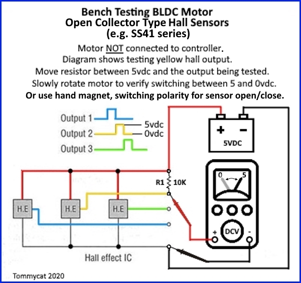
Newbie here Looking for some troubleshooting advice. I've got a brand new Bafang front hub motor that spun out of the front dropouts, damaging the wiring harness in the process and resulting in the dreaded error code 8 coming up. After much poking around on the interweb and pointless interactions with the technical support team at BafgangUSA direct, I opened the motor up, cut out the damaged section of wiring and resoldered. Upon reassembly, I came up with the same result. Testing the connections with the multimeter, I found that the green sensor terminal was not switching on and off as the motor rotated. I replaced the green hall sensor no effect. All of the hall sensors appear to be working, switching on and off as the motor is turned, but the voltage at the main terminal of the small green wire doesn't change. In other words, switching at the switch, but not at the terminal. I've attached a handy info-graphic to illustrate the situation. Any advice is welcome.
Cheers
 

Attachments

  • 20210203_174347.jpg
    20210203_174347.jpg
    211.4 KB · Views: 714
dick slessig said:
Upon reassembly, I came up with the same result. Testing the connections with the multimeter, I found that the green sensor terminal was not switching on and off as the motor rotated. I replaced the green hall sensor no effect. All of the hall sensors appear to be working, switching on and off as the motor is turned, but the voltage at the main terminal of the small green wire doesn't change. In other words, switching at the switch, but not at the terminal.
Interesting that they actually have pullup resistors for the halls built into the motor's hall PCB. Normally motors only have the halls in the motor, and the pullups are all inside the controller, from the controller's 5v (or 12v!) to teh hall signal line. Thankfully this makes troubleshooting slightly easier for you, since you don't need a controller hooked up to test the halls. :)

First, if the controller *is* hooked up for these tests, disconnect it and retest, to see if you get different results. If you do, it might mean the controller itself is damaged from shorting battery voltage (on the phase wires) to hall signals (much lower voltage). :(

While you're there, you can also use the multimeter on continuity or the lowest ohms setting, and test to make sure that only the phase wires on the motor connector have connection to each other, and not to any other pin, and that no ohter pin has connection to any other pin. That makes sure you don't have any shorts inside the axle wires anywhere, leftover from the spinout damage.

If it's not switching at the pad (terminal) where the wire from the cable is soldered, but *is* switching at the corresponding hall signal pin's pad, then it means the connection is broken on the PCB itself somewhere between the hall's pullup resistor and the (terminal) pad.

To verify the break, disconnect power / etc from teh motor, and use the multimeter on continuity if it has this function, and lowest ohms setting, if not. Place the red meter lead on the (terminal) pad in question. Place the black meter lead on the hall signal pad in question. You should read nearly zero ohms, and/or get continuity tone.

If you don't, then place the black meter lead on the end of each of the little tan blocks (resistors) that is closer to the center of the motor. (taht's the end that appears to be used for the hall signal pullup; hte other end appears to be hooked to hall 5v power). This may require a slight bit of pushing to get the point of the meter lead thru the clear stuff over the top of the resistors...but don't push too hard or you'll break them off the board. :(

If you still don't get any connection, then move the red meter lead to the hall signal, and repeat the tests. You should then get no connection between hall and terminal but should get connection between hall and resistor.

If you still dont' get a connection, then the clear stuff on the resistors may still be preventing contact with them, and you might have to carefully remove it; this risks breaking the resistors off. :(

Alternately, you can see if the entire board can be removed from the motor (by undoing the screw(s) and then gently lifting it straight away from the motor, withotu bending the hall leads (they're fragile, so you don't want to pull on them or bend them). The halls may be glued into the motor, and if they are you won't be able to pull the board off.

If the board does easily come off with the halls, then you can measure on the other side of the board, where the vias (the little silvered holes) go thru; those are not only easier to measure at, they're probably where the problem lies--there may simply be a broken connection from the trace to that via on one side of the board to the trace on the other. Those are easy to fix by putting a bit of tinned copper wire or a piece of component lead thru the hole, and soldering it in place on both sides. :) Then trim teh ends so they dont' stick out enough to touch anything near the board.

If any of the above isn't clear, or doesn't help, post clear questions / results and I'll see what I can do. :)
 
Awesome. Thanks so much!
I've already done all the common sense continuity/short tests, so it seems to make sense to rule out the controller next. Since the power flows through the controller to the motor, I assume a small battery like a 9v is the appropriate power source?
 
Since these are powered from 5v on your controller, I'd reocmmend something that provides 5v, like a USB charger or similar. Then you know you are getting results that would match what your controller works with.

If you've verified continuity between where the signal reads correctly and where it does not, what is the exact resistance you read on the one that doesn't work vs the ones that do?

There has to be a difference, if the reading is different, because you can't get a voltage difference without a resistance to have a difference across. ;)
 
I knew that old 5v wall wart would come in handy one day. In your face, better angels of not-hoarding old electronic junk!
Anyway, here's what we got without the controller: 5v going out to all the halls, but nothing coming back to the pad. 5v at the white wire, but nothing else. Continuity (but no voltage) from the hall terminals all the way to the wiring harness connector pins. No detectable shorts.
 

Attachments

  • 20210203_174347-2.jpg
    20210203_174347-2.jpg
    210.8 KB · Views: 665
dick slessig said:
I knew that old 5v wall wart would come in handy one day. In your face, better angels of not-hoarding old electronic junk!
Anyway, here's what we got without the controller: 5v going out to all the halls, but nothing coming back to the pad. 5v at the white wire, but nothing else. Continuity (but no voltage) from the hall terminals all the way to the wiring harness connector pins. No detectable shorts.

Ok, then there's something very strange going on.

Motor hall sensors like these don't output a voltage, they just ground whatever voltage is already present on the signal line whenever they detect a magnet passing. That's why you see 0V on all of them whether the magnets are passing them or not.


What this means is that the board does *not* have pullups built into it, because:
--if it did, the signals would still toggle high and low as the motor turns.
--Since they don't, it means that the controller has the pullups in it.
--Since the controller has the pullups, it also means that in order for the hall signal to toggle high and low *at any point* on it's wire, it would have to do so *for the whole length of the wire*, because:
--the controller is what is providing the 5v on the signal line (via internal pullup resistors) to be pulled low by the hall signal when it's active.
--if you can see the 5v at the sensor signal line, then since it can only come from the controller, there can't be a break in the wire to the controller.

But if the signal is toggling at the hall sensor but *not* at the signal output point to the controller, there *has* to be a connection problem that causes such a high resistance between that point and the sensor that it's able to drop the whole 5v across it while the hall is grounding the 5v on it's side of the problem. :/


So I still don't see any option for a problem other than a connection issue between the point at which you can see the signal toggling, and the point at which you can't. It can't be a complete break, just a relatively high-resistance point.


FWIW, based on the above, those parts on the board are probably noise-reducing capacitors instead of resistors.


(the white wire has 5v because it *does* have it's own pullup inside the motor; if you were to pass a magnet past the sensor connected to it (facing you on the board closer to the axle than the other sensors) you'd see it also toggle like the others).
 
But if the signal is toggling at the hall sensor but *not* at the signal output point to the controller, there *has* to be a connection problem that causes such a high resistance between that point and the sensor that it's able to drop the whole 5v across it while the hall is grounding the 5v on it's side of the problem. :/

This seems to be the heart of it. Unfortunately, the halls are nestled into the stator in a way that makes it impossible to remove the board without causing all kinds of havoc. The fact that we've got all the halls toggling properly when the controller's hooked up, and no sign of connection trouble between the halls and the connector pins makes me think that the connection problem must be in the controller-that the green sensor wire must be shorted to the red wire somewhere in the controller???
 
dick slessig said:
The fact that we've got all the halls toggling properly when the controller's hooked up, and no sign of connection trouble between the halls and the connector pins makes me think that the connection problem must be in the controller-that the green sensor wire must be shorted to the red wire somewhere in the controller???
Easy to test. Leave controler powered off for a few minutes, no connection to motor or battery. Set multimeter to lowest ohms. One lead to hall 5v. Move other lead to each of the controller's three hall signal wires in turn, noting the reading. If they are all very similar, then there is no short (at least, not in just one wire, and so unlikely to be the cause of the problem).

The same test can be repeated on the motor while disconnected. If all are very similar...it's not in the motor cabling, either.


Anyway, if it were a short from signal to 5v, without any other issue, then you wouldn't see the hall toggling. There has to be a resistance between the hall and the point the controller wiring connects to the PCB (terminal, pad) where the 5v is being "dropped" across, for the hall to be able to toggle the voltage without literally "shorting out" the 5v. (which would cause problems with the entire controller that you would notice; it would power off and the other halls and the 5v line itself would all drop to the same as the hall that toggles the line down.

So...we're back to there being *something* going on between the terminal / pad where the controller wire conects and the hall signal pin itself.

There is a small chance that the little chips on teh board *are* resistors (probably pretty low value), but that they are in *series* with the hall signals, to prevent damage to the halls in the case of axle wire damage. If this is the case, then that is where the 5v is being dropped across when the hall toggles, and you will see it if you put the voltmeter probes across the resistor that is in the signal line with the problem. Also, if this is the case, when ohming out / testing the continuity between terminal pads and the hall signal pins, you would be reading the actual resistance of those resistors.

If you can trace out the wiring of that board and draw it up on paper, it may help us see where all the connectiosn *really* are, and what the parts must then be, and then where to look for the problem. I can't quite tell where all the traces go because of the blurriness of the pic and because I cant' see the other side (which you'd have to trace out with the ohmmeter from this side; if you can shine a light "under" the board you can see thru it a little bit, letting you see where the traces on the bottom side go from and to, so you can verify they do so and then draw those into the wiring diagram.


If you were seeing all the halls toggle normally even at the terminal pads, but the system didn't work, then I'd simply say you have a damaged controller from the wiring damage (probable hall signal short to phase wire), and just replace the controller. (which may still be necessary).

But since you are also seeing a problem that can't *by itself* be caused by the controller unless that board is setup differently than the ones I've worked with and seen posted about so far (always possible), there is likely also a problem somewhere there. So figuring out how that board is supposed to work so we can make sure it is actually doing so ;) is necessary unless you just want to try a new controller to see if it fixes the problems. ;)
 
dick slessig said:
I knew that old 5v wall wart would come in handy one day. In your face, better angels of not-hoarding old electronic junk!

:lol: :thumb:

This may help to check the halls without a controller connected...

NktFBwJ.jpg


And put another way...
https://electricbike.com/forum/foru...nsor-testing-without-using-a-motor-controller

Other information can be seen here...
https://electricbike.com/forum/foru...-motor-s-phase-wiring-hall-sensors-and-wiring

I'd be suspicious of the soldered terminals if any strain on the wires was possible if you've thoroughly checked the wires for internal damage. (resistance)


Regards,
T.C.
 
I think I may have cracked it. In the absence of a schematic, I was operating under the premise that the phase wire colors corresponded to the sensor wire colors location wise, which it turns out is not the case. After more probing with the multimeter, I realized that my initial assessment of which halls were toggling or not was based on readings at the pad, not at the sensors themselves. Based on that flawed diagnosis, I replaced what I thought was the green hall sensor, but was actually the yellow one. After tracing the signal path (see attachment), I realized that the hall that's located with the blue phase wire connects to the green sensor wire, and that sensor indeed is not toggling. Luckily I bought a 6 pack of halls, so I'll replace that one and let you dudes know how it goes.
 

Attachments

  • 20210203_174347-3.jpg
    20210203_174347-3.jpg
    211.3 KB · Views: 617
Back
Top