Ricky_nz
10 kW
OK. A while ago I played around with an analogue hall sensor that I plan to use to control regen from the brake leaver for my motor controller project but since I'm still working on that one I thought I would knock up a quick circuit to use an on/off type hall sensor to control the brake light on my bike.
The brake light is a motorcycle one and has a common ground with the tail light circuit so must be switched in the positive wire.
I used the A3213EAU hall sensor. Its output is open collector and therefore high impedance with no magnetic feild and when the field goes over its internal threshold the output pulls low.
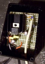
I used a TO-220 7805 because I also wanted to power my existing LED bike headlights off it. If that is nott needed then a 78L05 would be fine.
Heres the circuit. its a bit messy as it was just a sketch (I might draw up a tidier one later). the resistor values are very approximate. all 4K7 (Its one of the few values of leaded resistors I had as I have mainly swapped over to SMD these days.

View attachment 1
A small magnet on the lever and the sensor nearby or the other way round and it works fine on my hydraulic brakes.
The PNP transistor is a BC557 similar and the NPN a BC547 or similar.
The output FET could be any P Channel FET that is capable of passing enough current for your brake light/LEDs.
The circuit could probably be simplified but I was in a hurry.
If you want a sensor for each brake lever you can just connect it in parallel with the first one. If either is activated the light would come on.
It should be possible to tap off and run ebrake inputs of controllers as well.
The brake light is a motorcycle one and has a common ground with the tail light circuit so must be switched in the positive wire.
I used the A3213EAU hall sensor. Its output is open collector and therefore high impedance with no magnetic feild and when the field goes over its internal threshold the output pulls low.
I used a TO-220 7805 because I also wanted to power my existing LED bike headlights off it. If that is nott needed then a 78L05 would be fine.
Heres the circuit. its a bit messy as it was just a sketch (I might draw up a tidier one later). the resistor values are very approximate. all 4K7 (Its one of the few values of leaded resistors I had as I have mainly swapped over to SMD these days.

View attachment 1
A small magnet on the lever and the sensor nearby or the other way round and it works fine on my hydraulic brakes.
The PNP transistor is a BC557 similar and the NPN a BC547 or similar.
The output FET could be any P Channel FET that is capable of passing enough current for your brake light/LEDs.
The circuit could probably be simplified but I was in a hurry.
If you want a sensor for each brake lever you can just connect it in parallel with the first one. If either is activated the light would come on.
It should be possible to tap off and run ebrake inputs of controllers as well.

