• Hello ES! We could use some help to get us past the finish line on building the new knowledgebase for the forum.
    Can you donate? Please see our fundraising page. Thank you!

Having problems with CAN Communication

aleikxandro

🔌 New-ish
Joined
May 14, 2025
Messages
16
Location
Spain
Hello everyone,

I'll try to explain my situation so that anyone who knows something about CAN communication or how Ixxats work can help me.
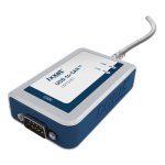
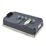
Alright, so I'm building an electric motorcycle, and I've got an inverter Gen4 Size6 (I attach the images) 72/80 V nominal voltage and 500 A peak current. I also have a PMAC motor which is not the problem, becuase it has been tested on a test bench and it surely works. The main problem comes with the communication program and the Ixxat USB-to-CAN V2 compact con D-Sub-9 with galvanic isolation.
So, I know they are quite easy to break and they tend to when not manipulated properly, and this is a very important step to be able to communicate from my computer with the inverter, since the program used from Sevcon (Borgwarner), DVT Customer Application and CAN Analyser 3 Mini with the VCI Driver installed and updated, specifically need an Ixxat of the ones I have attached in the third image to work properly. In addition, they say that if it is any other type of Ixxat than the 3 shown in the images, it is not sure that they will work as they have not been tested.​
We have made measurements and tests, we are practically sure that our Ixxat is broken, it does not send or receive data, although it recognizes the CAN bus, it does not recognize the CAN communication and gives errors for everything. Although we have tested it with different Raspberry Pi systems, computers, inverters and laptop, etc.... Fixing it is not an option due to time and shipping issues. I would like to know if anyone knows of a cheaper Ixxat (because they are usually quite expensive even exceeding 300€) that works for my inverter model and can communicate with it from a laptop or microcontroller easily. If someone can help me to recognize the CAN and configure it so I can start with the programming of my inverter and test it with the engine on a test bench I would also appreciate it. I will also attach the main errors recognized by the microcontroller.

Thanks a lot people.
 

Attachments

  • 1.01.0281.11001-700x700.jpg
    1.01.0281.11001-700x700.jpg
    43.3 KB · Views: 6
  • 0U1A8223-Custom.jpg
    0U1A8223-Custom.jpg
    78.2 KB · Views: 6
  • Captura de pantalla 2025-05-17 144804.png
    Captura de pantalla 2025-05-17 144804.png
    100.7 KB · Views: 6
  • IXXAT_canAnalyser3_Mini_25-05-16_195127.csv
    18 KB · Views: 3
  • IXXAT_canAnalyser3_Mini_25-05-16_200809.csv
    1,015.7 KB · Views: 1
Have you tried sniffing the bus for traffic with an external analyser? They're quite inexpensive and should tell you what's going on on the bus, electrically.
 
Have you tried sniffing the bus for traffic with an external analyser? They're quite inexpensive and should tell you what's going on on the bus, electrically.
Yeah, I've tried with an oscilloscope, but it didn't work as it did not show any signal no matter how many times we tried to make different connections, data transmission, etc... Are you referring to a more specific type of external analyzer? Do you know of a cheap one that could be more useful?
 
Yeah, I've tried with an oscilloscope, but it didn't work as it did not show any signal no matter how many times we tried to make different connections, data transmission, etc... Are you referring to a more specific type of external analyzer? Do you know of a cheap one that could be more useful?
If an oscilloscope didn't show any signal, then you're like two steps behind diagnosing why the devices can't talk to each other. CAN has a very specific operation pattern that would appear in normal comms. Try each device individually and see if they appear operating correctly.
 
If an oscilloscope didn't show any signal, then you're like two steps behind diagnosing why the devices can't talk to each other. CAN has a very specific operation pattern that would appear in normal comms. Try each device individually and see if they appear operating correctly.
Yeah right, I'll try checking each device individually so that I can isolate the problem. However, I'm pretty sure the Ixxat it is broken.
Thanks a lot man, anything you think of I'll be reading your messages!
 
If you get nothing but a flat line on the scope, with the scope ground on the CANbus signal ground, and the scope signal on the canbus signal line, using vertical settings of 2v/division or 5v/division, and maybe 1ms-0.1ms horizontal, with autotrigger / autolock (whatever yours labels horizontal sync as), then there's either something wrong with the scope or probe, or there is nothing being sent on the bus.

If nothing is being sent on the bus, the hardware itself is probably damaged, probably the tranceiver, which you can probably replace (at a guess, its' probably a single chip. This thread has some info Ixxat CAN-Compact V2 fixed

Does the scope have a calibration hook/pin? If so, connect your probe to that to make sure your probe and scope are working. It'll be labeleld with what signal it puts out, so you can set the scope correctly, but it will probably show a signal with the same settings that canbus can be read with.
 
If you get nothing but a flat line on the scope, with the scope ground on the CANbus signal ground, and the scope signal on the canbus signal line, using vertical settings of 2v/division or 5v/division, and maybe 1ms-0.1ms horizontal, with autotrigger / autolock (whatever yours labels horizontal sync as), then there's either something wrong with the scope or probe, or there is nothing being sent on the bus.

If nothing is being sent on the bus, the hardware itself is probably damaged, probably the tranceiver, which you can probably replace (at a guess, its' probably a single chip. This thread has some info Ixxat CAN-Compact V2 fixed

Does the scope have a calibration hook/pin? If so, connect your probe to that to make sure your probe and scope are working. It'll be labeleld with what signal it puts out, so you can set the scope correctly, but it will probably show a signal with the same settings that canbus can be read with.
When we tried to connect the scope to the Ixxat (yes with the scope ground on the CANbus signal ground and the scope signal on the CANbus signal), at first we got a flat line just as you said, but then of a sudden it began to show a flat line with some noise, like a square signal in a very light color.

So, we sent messages from a laptop to a Raspberry (we also tried first with an inverter) through the Ixxat but nothinh was sent on the bus. Is there any possibility that, instead of the tranceiver there's another part of the Ixxat damaged that you can think of? We are discussing that maybe overloading the bus with error messages may cause something in the ixxat to break or something like that? We tried to sent only a few messages, but when we saw nothing was being received we started sending more.

I've read the post you sent me before and it was quite helpful. I remember how my Ixxat got warmed and I didn't checked the output voltage level, so that may be a thing.
Thanks a lot for the help also dude, I appreciate it very much.
 
I don't know the ixxat design, so you'd have to try tracing signals from input to output and see where you stop getting any.

The other thread PCB images show it has an MCU (the big chip) so most likely all input signals go to that, and are processed based on whatever software the Ixxat creator wrote, then are sent to the output, in both directions. That means that unless its a transceiver failure, or a voltage regulator failure that left it without power (as opposed to sending unregulated voltage onto the power bus, which would destroy things connected to that bus), it's probably not user-fixable.
 
I don't know the ixxat design, so you'd have to try tracing signals from input to output and see where you stop getting any.

The other thread PCB images show it has an MCU (the big chip) so most likely all input signals go to that, and are processed based on whatever software the Ixxat creator wrote, then are sent to the output, in both directions. That means that unless its a transceiver failure, or a voltage regulator failure that left it without power (as opposed to sending unregulated voltage onto the power bus, which would destroy things connected to that bus), it's probably not user-fixable.
That really makes sense, I'll try checking both things with my Ixxat. I hope that it still is usable, but I don't really think so.

Thanks a lot man, you've really been a great help :D and I'll keep you informed in this thread on whether it works or not (probably Monday or Tuesday).
 
Hello everyone!

I just wanna update this thread to say thank you to everyone, especially to @amberwolf for lending me a hand when needed.
The problem was "solved", it was the transreciever and and a galvanic signal isolator that had short-circuited and therefore stopped working. As we had two Ixxats, the 12001 and the 11001, we decided to repair the old one ourselves by buying and replacing the components while sending the new one to the original distributor for repair. We noticed an inoperative voltage drop of 0.6 V instead of the approximate 2.5 V required.
So, as soon as we get the repaired one we can start with the CAN communication and programming our competition motorcycle's inverter.
A hug to all and thanks for your contribution!​
 
You're welcome--if you can post pics of the board showing what to replace, and list the parts you used to replace them with, it will help others that have the same problem. ;)


Also, OT, but what music do you make with your bathtub setup in your avatar? (mine is at the bandcamp link in my signature)
 
You're welcome--if you can post pics of the board showing what to replace, and list the parts you used to replace them with, it will help others that have the same problem. ;)


Also, OT, but what music do you make with your bathtub setup in your avatar? (mine is at the bandcamp link in my signature)
Yeah sure! I'll post some pics and info about it as soon as I repair it (next week probably). Also, I'll explain what the distributor says about the broken Ixxat. :D

Oh ahhahahahah, nah I don't do music.... My profile pic is just a screenshot of and old youtuber which used to make content (now his artistic name is Joji I think). I listened to your music at the bandcamp link and I really enjoyed it! It has style and its really unique like expressing yourself, keep it up man!
 
Hello everyone again!

How are you all doing? You see, I didn't abandon the forum or this thread, far from it.
Over the last few months, I've been trying to solve problems, and for months I succeeded. Communication was working properly and I managed to get the inverter to run without any LED faults.

However, from one day to the next, a catastrophe occurred because my Gen4 Size 6 72/80 V inverter connects to an Ixxat USB to CAN V2 compact and is programmed using DVT (your program). When attempting to ping node 1 (master node), it detects the bus-off and does not connect even though the inverter has a heartbeat and the green LED is flashing. There is only one CAN node since the inverter is directly connected to the Ixxat and everything is read via a laptop. The resistors are properly connected, 120 ohms in the Ixxat DSUB9 connector between CAN_HIGH and CAN_LOW and another internal resistor in the inverter of 120 ohms (again, between CAN_HIGH and CAN_LOW), both in parallel and giving the 60 ohms that the CAN should have.

Attached is a photo of the error directly from the DVT.

I have checked that the Ixxat is working and the inverter connection is correct, I have also tried all possible baud rates for the inverter, what can I do? Is the bootloader or the inverter CAN not working?
I also tried changing the DSUB9 connector as it can sometimes cause problems.

Thank you everyone for your help!!

PS: I have discovered quite lots of things about this inverter, the Ixxat and communication, and I'm looking forward to send you guys all the information. So I'll keep an eye in this thread and forum
 

Attachments

  • captura_inversor.png
    captura_inversor.png
    97.4 KB · Views: 3
Hello everyone.
I hope this post finds you well, just so you know, the ultimate problem is that the inverter's CAN bus is probably fried.
A voltage spike along this bus will have caused the inverter's CAN transceiver or a similar component to stop working and broke down. So yeah, my sevcon is fried 😅.

My recommendation (in addition to not using these inverters) is to be very careful when touching pins, Ixxats, or the inverter's wiring in general with your bare hands. This is because what probably destroyed my CAN bus was an electrostatic discharge that we caused when touching it with our bare hands in an environment with many nearby charges (similar to what could happen if you touch metal after rubbing yourself against a carpet).

Keep this in mind for the future, and buy a Kelly, which is much simpler to use and offers very similar or even superior performance. Unless you are looking for maximum customization of the inverter software and have everything very, very well set up.

Thank you everyone in this thread for following my story and giving me advices, you're the best!!!
 
Back
Top