Amberwolf's Schwinn Trike Rebuild / Conversion to Heavy Cargo Hauler
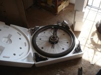
From here: https://endless-sphere.com/sphere/threads/the-sb-cruiser-amberwolfs-2wd-heavy-cargo-trike-dog-carrier.67833/post-1827806 I got an old Schwinn Tri-Wheeler Town and Country (probably the 1971 or 75 or 78 model, based on info from bikehistory.org) from someone I knew from the...
There are mulitple possibilities; I don't presently have a set design in mind, just a goal of being able to drive both rear wheels from the system, without preventing the pedals from still doing their job the way they presently do. (the front wheel is taken care of separately).
The requirements are that it reaches the max of 20mph pretty quickly (say, 5-6 seconds worst-case) from a stop even with say, a 400lb load (me plus the trike plus some cargo; this one doesn't have to be as hefty as SBC which could do double that loading), and that it leaves the pedal drivetrain still working as-is, as much as possible, as a backup in case of all motor system failure. It has to be cheap, preferably built entirely with stuff I already have (just buying tires for this build is more $$ than I really have available, and I'd like to get a "new" battery to use on it).
The simpler the design and build is, the better, as it's more likely I'll actually finish it in a useful time.
")
The trike currently has cranks that drive the input to a Shimano 333-variant 3speed IGH that then drives a (peerless?) differential on the live rear axle to the 24" rear wheels.
The trike will change so that the rear wheels aren't on the axle ends anymore, but use 26" wheels on stub axles mounted to an extension frame to lengthen the trike and expand the cargo area (and move the seat back). Sprockets will go on hte live axle in place of the wheel hubs, and a chain from each of those to sprockets on the new wheel hubs on the stub axles will then drive the wheels from the pedal system.
The motor can input to any part of this system, but I expect that doing it to the IGH shell (effectively the diff input) will be mechanically the easiest; I can add whatever sprocket to the shell easier than I can to the diff.
I wouldn't mind inputting to the IGH input along with the pedals, but that would force the pedals to turn if the motor is turning (without adding more freewheels to the system, complicating the design and creation, which I am trying to avoid--the more work it is, the less likely I'll ever get it done).
If the motor would be better off with the ability to shift gears between it and the wheels, I can do one of several things:
--add a cassette/derailer (have IGH's but don't think I can use them in stub axle mode; see **** later in post) on each rear wheel, with the shifters tied together so they shift to the same gear. That would also add gearing for the pedal drivetrain if I needed it (unlikely).
---add a shiftable drivetrain between the motor and the diff input.
--probably other options i'm too tired to think of ATM.
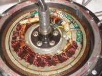
I have a number of common ebike brushless hubmotors (some DD, some geared) that can be used to drive the system in one way or another..
I also have powerchair brushed motors with gearboxes that already have stub axles that can probably take the necessary loads, but tthis wouldn't be a middrive, and would preclude using the pedals to drive the wheels as backup to motor failure, unless I built a clutch system (like many geared motors have, etc) between the stub axle and the wheel hub, and put the pedal chain input on the hub side of that. There is one option that wouldn't preclude it, and that's if I can use the older gearbox type (I might have two of) that has a mechanical clutch inside to disconnect most of the gearing from the output shaft (to allow a human to push the powerchair they came from, if the power failed).
It would probably be easier (to preserve the pedal drive train usefullness) to use the gearbox output to drive the diff input.
Both the gearboxes and the hubmotors are easy to gear to the same rrpm range that the pedals would have; I did this for CrazyBike2's "best" middrive system that used this type of motor.
**** If it were possible to use them as stub-axle wheels with the heavy load they'd have in this use, I've got a couple of SturmeyArcher (or SRAM?) IGH + drum brake wheels from the ex-JumpBike sale a few years back. That would give me brakes *and* gearing on those wheels. But I can't imagine those axles would handle this kind of abuse.
The stub axle design is not an absolute requirement...but I would like to explore it and test it in this design, as it makes wheel/tire work roadside MUCH easier--I can literally just pull the wheel off and swap it out with a spare to get going, or I can easily access the tire/tube/etc without having to unload the trike and roll it on it's side to get the wheel out of the frame like I do on the SB Cruiser trike, etc.
If I can't use a stub axle, I can build the frame so it is a tiny bit like the old cadillacs with the body covers over the wheels, though in my case it would be a structural frame that can be unbolted with a QR on one end and swung out off the outboard axle end to get it out of the way of the wheel. (another feature I'd like to build and test anyway, as I always wanted to do this for the SBC but haven't had a spare transport while doing the experiment in case it didn't work out and had to be undone or revised repeatedly).
If I had two of them, I'd use the brushless powerchair motor that mounts to the frame and has it's own stub axle inside, and the motor is the hub. Then I'd just build bolt-on spoke-flange adapters for that to lace the wheels up on. But I've only got one, and I haven't found affordable (super-cheap) ones I could get another identical one of (or a pair of that are different from mine). But all this is getting much more complicated than I'd like...I'd much rather just drive the pedal drivetrain and have a lot lest custom stuff to do.
I'm sure this is not enough info yet to come up wiht something useful, but my brain is turning off (still have a head/chest cold that's no fun), so will just post it and see what responses there are,a nd work from there.