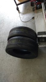
I don't always drive like that and a buddy is a drifter so I got some awesome deals on any tires I wantfechter said:Very impressive. Bet the tires won't last long.
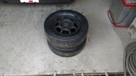
") I also have DOT drag slicks on their way
I also have DOT drag slicks on their way I don't always drive like that and a buddy is a drifter so I got some awesome deals on any tires I wantfechter said:Very impressive. Bet the tires won't last long.
I also have DOT drag slicks on their way liveforphysics said:Arlo1 said:I think you start by looking at what models come with a lsd.....Punx0r said:Any chance Nissan raided the parts bin for the Leaf's diff? I've got a feeling the answer is "no" considering how different the whole transmission is to their multi-speed ICE cars, but you never know...
Mind you I've never held or measured or anything to a LEAF differential. That said, I have installed quite a few Nissan differentials for FWD and RWD. You wouldn't expect it, but it's an enormous year-range and model range for Nissan's that can swap LSD differentials. This doesn't mean that the LEAF may not be it's own unique thing, but just as a data-point, you an swap LSD's between a BUNCH of models of Subaru and a BUNCH of models of Datusn/Nissan and a BUNCH of models of Mazda and amazingly, and over a rear-range of like 1975 to mid 2000's. They typically just need a different ring-gear bolted onto the LSD, and occasionally different sized bearings pressed on, but otherwise it's extremely handy how they basically standardized the differential on so many models across mfg's for so many decades.
I would say it's at least worth investigating what may fit for LSD in a LEAF for a street car. If it's a track car and you're on slicks, I realize this controversial and counter-intuitive to claim, but LSD or open diff makes essentially ZERO difference in a car running drag slicks on a sticky track. I couldn't tell you why exactly, but from decades of observations, an LSD or no LSD at the drag strip makes essentially no impact on torque steer or 60ft times.
On normal asphalt on normal street tires it makes a very notable difference to have an LSD.
I ended up making some modules from some used EIG cells.fechter said:I know it's probably in the topic somewhere but I can't seem to find it in less than 1 minute, What are you using for batteries?
i guess that's why they good :wink:And the GOOD RC packs are outrageously priced
HighHopes said:i guess that's why they good :wink:And the GOOD RC packs are outrageously priced
for our open source discussions.. the battery pack should become a topic of discussion. we want good traction packs that we can reliably get the energy out of that we want at a fair price. is that on the market? if yes, then no issue. if not then we'll need an offshoot discussion on battery pack design. maybe not today... but soon..
liveforphysics said:I can help a bit with this.
First page.Tomdb said:Arlo,
Could you run me through some details of your install. Since you seem to be having alot less issues with emc. Mind posting a pdf format of your schematic?
Seeing that your brain board is outside the inverter with the phase wires going into the inverter, what kind of cables do you use, shielded?
Also are you shielding the phase current sensor wires?
On your board I do not see any isolation between the IC and driver chips on your gate drivers, is this true?
Enjoy the journey 
marcos said:Hi Arlo,
one thing I saw in your gate drivers (leaf and gamechanger) is that you should have larger cleareances between the traction pack side and the controller side. I see 1.6 and 2mm as the shortest path in the leaf.
For safety concerns, medical devices for example must have 5mm cleareance and 8mm creepage for a 240V application. It can be less if the board has a lower pollution degree. A large cleareance also means less pF between the control side and the igbt side.
To avoid risks on your boards you can do some conformal coating or silicon potting to extend spacings and to improve the pollution degree. If you already do this, please make that clear in the 1st post.
Indeed, it is a lot, I had a lot hair pulling because of that, but it was required to sell a particular product. You're by all means free to use the clereance you want, I'm just pointing this out as a suggestion.Arlo1 said:8mm is a lot. The gate driver it self its only 7.5mm from the input to output side and it has a "• Safety approvals:
UL approval, 5000 VRMS for 1 minute, CSA approval,
IEC/EN/DIN-EN 60747-5-5 approval VIORM = 1414 VPEAK" So I wish you luck with 8mm. The trace you measured there is on the top and the ground plane you measured to is on the bottom so that is not a measurement of clearance.
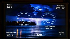
Nice dashboard! Is that a rpi?Arlo1 said:Working on some gauges as well.
hillzofvalp said:Speaking of production...
when will you offer kits so I can put on of these in my leaf with fresh 2016 pack? I'm sure it will still be fun with a stock leaf pack... not quite as fun as 470V with 150C pack, but probably still 300% improvement.
It's your choice..... But the easiest way to make a leaf faster is to program it to go fasterhillzofvalp said:What does it take to modify the oem controller? Are you talking about a firmware rewrite?
Maybe it would be easier to remove most of the car and canbus