High power battery tester

Teh Stork

1 kW
Joined
May 25, 2011
Messages
463
Recently I was allowed to drop all my compulsary labs in a embedded design class, and develop a battery discharger/cycler. Delivery of a build report will be the substitute for the labs.

Scope of project
Research possible solutions and build an automated battery tester that can handle high power batteries (0-100V, 0-50A)

Motivation
Gain more experience in embedded design
Aquire suitable test equipment

Functionality
Internal resistance test
Capacity test
High continous discharge capabillity, ~2kW
High peak discharge capabillity, 10-15s ~5kW discharge
Selectable discharge mode: Constant Current, Constant Power
Temperature monitoring
Datalogging

I'll make this thread a build log/research log. Updates will be posted in this thread, it will work as my journal.
 
Passive or active discharging
By turning the energy drained from the battery into waste heat, all the energy is wasted (passive); This is the easiest solution. By simultaneously discharging one battery and charging another (active), only losses in transmission would be turned into heat. For this application, passive discharging is deemed suitable.

Getting rid of heat
For continous high output, hair dryers are looked upon as suitable. Small, light weight and cheap.
84-155_m.jpg

For intermittent high output, water heaters could prove suitable. Also light weight and cheap, but the humid output is unwanted.
28-499_m.jpg


Contents of the black box
The battery delivers low voltage (0-100V) DC. This must be turned into high voltage (220V) AC or DC, as used by the heating element. The applied load can be easily changed with a contact splitter.
46-321_m.jpg


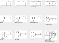
The voltage conversion can be done several ways
file.php

Of all these different choices, full bridge looks like the best solution. To keep the overall size small, the transformer will be operated at high frequency (20-40kHz). The output will be rectified before leaving the converter.

The embedded part of embedded design
The brains of this project will be the A3BU Xplained evaluation board from Atmel. The same price as an arduino, but with features far surpassing it.
XMEGA-A3BU_Xplained_top_side.jpg

Notably:
Based around the Xmega microcontroller
32x128 screen
64Mb onboard flash memory
USB communication
12bit ADC
Suitable PWM outputs
20ppm crystal
 

Attachments

  • topology_choices.png
    topology_choices.png
    17.2 KB · Views: 994
Measurement quality
Battery current will be measured with a shunt resistor. A simple noninverting op-amp will condition the signal before entering the ADC. The single ended range is 0,05*Vref to Vref for the Xmega ADC. Vref is 2,06V. Therefore a small 0,15V offset is added, to ensure there is a stable offset.

Battery voltage will be measured through a kelvin connection where the test bench is connected to the battery. A resistive divider will downscale the result into suitable ADC range.

Accuracy
Much alike the Cycle Analyst, separate windows for calibration will enable the user to calibrate the V/step and A/step values.

Precision
The onboard 20ppm crystal will be the time reference used in the measurements. The error from this can be negated. (2 seconds error in a day)
Given 5-100V voltage range, no averaging: +-13mV (12 bit precision)
Given 0-50A current range, no averaging: +-6mA (12-bit precision - 5%)

With averaging, 16-bit precision should be attainable.
 
A load simulator is essential. #2, right behind a DVM.
i built mine 7 yrs ago for $10. it is not fancy like yours, but it gets the job done.
Anyone not able to test cells on the bench, is not playing with a full deck.
 
I do have a ~2A NPN based one, but it is manual - with a potmeter to control current. At high voltages it gets really hot aswell, so not for extended use. I miss a high power one, and while I think this project will leave me with a good battery tester - I also want to leave room for charger testing and the like.
 
Power conversion
Transferring power from the battery to the DC high voltage bus is one of the challenges in this project.

Full bridge
While the schematic for the full bridge looks like trouble, code to drive the full bridge is quite easy to implement. Two PWM channels are initialized in phase. When in phase, no voltage difference exists on the transformers taps - and no power is transfered. When a phase shift is introduced, a voltage difference appears on the transformer taps, and power is transfered. (If I'm not mistaken) maximum power is transfered when there is a 90degree phase shift. Creating a suitable transformer from ferrite, able to handle high power, is a big challenge. The scaling, in particular, is challenging.

A full bridge implementation requires two silicon diodes, four MOSFETS, two half-bridge drivers, one transformer, one inductor and an output capacitor.

Boost converter
A boost converter is very simple and elegant. The problem here is the big voltage jump, a 4x amplification in voltage gives high ripple currents on the output - but a large capacitance to smooth it out works. Another problem is that there must be a buck front to stop current flowing right through the diodes - to the load. There is a slightly more elegant way.

Multi stage boost converter
Splitting the voltage boosting up into several steps makes it possible to use MOSFETS with lower voltage rating. Using interleaving can also reduce the total current ripple.

Going for low voltage all the way - might be better. Firsly, no lethal voltages.
 
When you assemble individual cells into a battery pack, thermal testing from single cells will not be sufficient to accurately predict pack heating. Also, modern day single cells has already been factory tested. As for supply from grey market China, sure - test cells before assembling them into a battery.

This battery tester should be able to quickly test internal resistance. For new, and old, batteries this is a clear indicator of health.
 
Possible better solution

Going through the least amount of transistors and magnetics, before being dissapated, will give the cheapest implementation. Recently I found some AWG15 stainless steel (no zinc or tin to burn off) wire.

19-004_l.jpg


Stainless steel resistivity is around 41 times that of copper. 0,4 ohm/meter is a suitable estimation.

Using a buck topology would be enough to control the discharge. Definitely cheap and also easy to control.

I'll try to shoot straight for 2kW trough one ~3m (1,5Ohm) long coil, not sure how to shape it yet. A fan will cool the coil, but if this proves to be too much power; I will have to make a bigger coil.
 
good idea! How about rebar wire? What is the resistance of regular steel?
SS is better since it won't rust, but the rebar tie wire is at any home depot.
i'm going to try some for current limiting when charging with a psu. should make it easy to adjust amps by sliding an alligator clip along a length of wire.
 
Normal steel is a poor conductor of electricity. I am quite sure normal and stainless has similar properties. The reason I don't use rebar wire is that it is allways galvanized the stuff I can find for sale. If heating up this wire, the zinc will evaporate - and you don't want to breathe in the fumes. Any welder will testify to this. Of course, when it is evaporated (900C), it can be used as intended with no hazard.
 
mine is no. 16 from ace hardware. not galvanized, the label is torn, "an....."
could be anodized?
any problems with anodized fumes?
EDIT: i've put ss wire on my list. i'm almost out of rebar wire and it tests low ohms. and it rusts, so my next roll will be ss. many uses from hanging pictures to charge amp control.
 
Over the last three days, I’ve made much progress.

I continued on the buck based setup, a sketch was drawn on paper.


This was then turned into a schematic in Altium Designer.


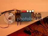
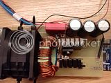
After scavenging parts from different boxes, I had just about what I needed to make the circuit. The parts ranged from the very tiny MOSFET driver, to my handmade toroidal inductor. A crude layout was sketched on paper.


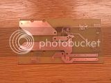
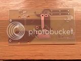
Everything was measured up and a PCB was made.


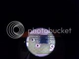
That small mosfet driver I mentioned, it was a pain to solder, but it is not my first time with small components – so it turned out OK.


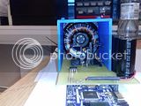
A 2mOhm shunt is mounted. 40A discharge is the goal, and this shunt might run into temperature issues in a normal application. This shunt is placed inside the «wind tunnel», so hopefully the spesifications can be stretched a bit. A server PSU was gutted for the high power fan. This fan delivers around 2m^3 air pr min. A nice feature, and the reason this fan was selected, was it’s controllable fan speed. At maximum power draw, current is 1,3A. At minimum draw; 60mA. The logic on this is 3V3 and is connected to PC6 on the Xplained kit.


A IRLB4030 N-MOSFET and a STPS 80150 Schottky diode make up the buck based converter. Switch speed can be very high since the junction capacitance of the selected schottky diode is low (800pF at 10V, 400pF at 50V). For applications with even higher power, a half bridge driven synchronously would be a good solution.


A 3D- printed part is attached to the delta fan. This duct is meant to ensure the semiconductors and circuit has enough cooling. This way, the design can also be small.


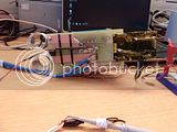
The heating coil was made from 3 meters of 1,5mm stainless steel wire. The shape of the coil and turn counts resulted in 7uH inductance. Time will tell if this can dissapate 2kW.


Voltage sense cables with Anderson connectors.


Power up went without any trouble. Tested the fan, crazy powerful. Tomorrow I'll start on the software development.
 
Hillhater said:
If you are boosting the voltage up to 220-240 v ..why dont you just use an old 2-3 kW convection heater for the load ?

I changed my mind. Boosting the voltage up to 220-240 V is harder than coiling this SS-wire and using a simpler topology. If not, a convection heater would be perfect.

nechaus said:
very nice, your doing a great job, im keen to see if those coils can do 2kw without glowing,
Thanks :) Looking forward to getting some data on the coils - hopefully soon.
 
If you need high discharge testing, I'd suggest to contruct a two-way DC/DC converter. This way you will be able to charge the battery and discharge it regeneratively. This mean getting the energy out of battery and not wasting it into heat, but transferring somewhere else. For example another battery. Schematic looks like this:
CCCV mode PSU -> buffer battery <-> DC/DC <-> battery under test.

This way you will lose very little energy ($$). And will have no problems with heat or big heavy equipment to dissipate it.
 
if somebody else wants to build a simple bench tester, just wind the ss wire in a way that it won't short or contact anything that can melt or catch fire, and put a few switches along the wire for various amps. everyone needs a way to test cells on the bench! A fixture to hold the wire, and switches is all, no other electronics needed. well, maybe a fan for high drain. say a 20" window fan if you have one. if the wire gets red hot, STOP. double up the wire and make it twice as long. a way to test cells is essential for every ebiker imo.
.
tested some 15a fuses at 15a and found half to have excessive heating! twice the voltage drop of the better ones. just an example of why a bench tester comes in handy, either a fancy high tech one like Stork, or a no frills one like mine.
 
I like the idea Circuit, but alas – for my use this is too costly. I used the opportunity to include a small analysis for my report.

Cost of test

In a capacity test, all the energy is turned into heat. Charging one battery while running the discharge test would improve energy efficiency – and thus you would save money on your energy bill. But the cost of this regeneration, charge, is not calculated, so what is the real cost?

The cost of 1kWh of heat is, in Norway, around 1 NOK (Both cost of transmission and energy cost is taken into account). A semi-real battery, containing 1kWh costs around 7800 NOK in Norway. This battery is rated at 1000 cycles to 70% capacity. This means every cycle costs 7,8 NOK. If the charge wear on the battery is set to be the same as the discharge wear, cost for one charge is 3,4 NOK.

If you can deduct the 1kWh energy saving, the cost of directly turning the energy into heat is at least half the price than regenerating it.

Combine this with the fact that for a 5C discharge test on a big battery, you would at least need 5x the capacity in batteries being charged. This means big investment costs in batteries and in discharge test equipment gear. In addition, heating housing is a big capital expense in Norway; 70% in normal houses and 50% in other housing. The energy being turned into heat is likely to be of good use.

The battery tester will mainly be used for ebike and motorcycle battery packs. This means 2-10C discharge tests will be common. As tests from NASA has shown, charging speed has a direct influence on battery life (slower charge favoured).
Resistive heating is therefore deemed the best solution for today’s demands.

As I do have to deliver a report written academically, I added some background to easier fill this in later.

I've focused on software developement lately. Current sensor offset and gain calibration is finished and also voltage gain calibration. There is a minor problem with the current calibration. Somehow, the offset does still read 2-4 ADC counts (this is 0,2-0,4A offset of full range) in offset. Oversampling will be implemented, hopefully it will solve this.

All calculations are done real time in fixed point math on the microcontroller. Building a user interface with two buttons has proved to be doable, but it is not efficient (Anyone with a CA can testify to this). If another revision is to be made, some extra user input will be implemented.

I tried the circuit with a 15V 6A (90W) load today. Parts didn't get warm at all. Monday I'll have access to a IR camera. With this present - I'll hook up this to a 51V 3kW server supply and do some high power tests to see how it holds up. Definitely looking forward to this :D Already I think the PCB-heating coil interconnect will have to be redone. I can bear a 5-600 degC coil as long as this heat is being convected away - and not conducted into the PCB.
 
Today I finally managed to sort out the drivers and software to the thermal camera. Testing started right away. Initially the MOSFET would reach 70degC at a measly 350W power. The cooling fin was disassembled and new thermal paste applied. The gate resistor was halved, from 22ohm to 10 ohm. With 11V supply, this should give about 1A gate drive. Additional leads was soldered onto the DS of the MOSFET to evaluate switching performance.


As can be seen, switching is clean with little overshoot.


Unfortunately, the onboard current reading will not show the proper reading. I will debug the code later. A multimeter was used up until 500W (10A load). This worked nicely with about 55 degC on the back side of the heatsink. I wanted to try higher power, so I disconnected the multimeter and went ahead with no instrumentation. My best guesstimation is that I ran about 1kW through the circuit at this test. The heatsink of the MOSFET reached 80 deg C – a bit out of my comfort zone.


The coil did what it was supposed to and got really hot. The discoloration indicates that some parts reached a peak temperature of 500degC. My camera does not fully do the discoloration justice.


So, there is basically two issues with the circuit. Nonfunctioning current measurement routine and a MOSFET that is running a bit hot. The first issue should be out of the way after some tiresome hours of debugging. The second I think I’ll solve with two improvements. Firsly, switching frequency will be reduced from 100kHz down to 60kHz. Secondly, switching speed will be increased by lowering the gate resistor. Below are overview images of the board, and the testing area.


Can the coil handle 2kW?
I really don’t think so. The resistance change in stainless steel over temperature isn’t specified. But if it is the same as iron, the coil resistance would double in resistance, making the set current impossible to reach. Can the coil handle 1kW? Definitely yes.
 
Turns out that the maximum power this revision will do; is 27A at 50V - around 1350W that is. The coil visibly shines red in the middle of the fan output - the direction of the fan is really hitting the edges of the coil.

The weird part is: When plugging in the values, the "hot" coil resistance is 1,8 Ohm. This is only a 40% increase from the original resistance of 1,35 Ohm. The peak temperatures of the coil is around 700 deg C, so the rest of the coil must have a lower temperature - or I have the temperature coefficient wrong. The temperature coefficient for iron is 0,006 per deg C. This 40% change in resistance would only be 70 deg? (my quick calculations are surely wrong)

As I upped the Duty Cycle from 80% to 100%, the MOSFET heatsink went from 80 Deg C, to only a couple of degrees above room temperature.


Yeye, this was really the "end of life" test of revision 1. It has kept up nicely. Now I'm looking forward to revision 2.

Stay tuned for:
  • External ADS1247 ADC, no more internal XMEGA ADC
    Heating coil of at least 6 meters (up from 3)
    Very low heating coil resistance, about 0,3 Ohm. Down from 1,3 Ohm
    A "solenoid driver" type of converter, instead of "buck converter" discharge style. This decreases switching losses. (simply the same setup, simply discontinous current - no more powdered iron core)

At the same time, the "embeddedness" of the project is split into more pieces. The electronic load and the instrumentation are no longer dependent on each other. The instrumentation can be put between the inverter and battery to datalog a ride or charge accurately.
 
Back
Top