Hi Matt,
recumpence said:
Mitch,
I am open to anything. My RC helicopters taught me to listen to those who buy products, but keep an eye on production cost. I have thought of a few options for downtube mounting. If this looks to be the main desire of most buyers, I can design an entirely new drive that is layed out specifically for downtube only use. That would be cheaper to make and more elegent. It will be far less universal, though.
Matt
I am aware of the following bikes (built or proposed) with your drive that
don't use a downtube mount (3 bikes):
Ben's recumbent
Gary's 2 Folding Dahon's
I am aware of the following bikes (built or proposed) with your drive that
do use a downtube mount (6 bikes):
Matt's PK Ripper
Oofnik
Decanio
* Gary's 2 townies
** Ypedal's RC build
* I don't know if Gary is committed to a downtube mount but if you make a drive for that purpose that is cheaper and more elegant it would probably be his first choice (particularly if its easier to mount
")
).
** I don't think Ypedal is committed to a downtube mount but he appears to be considering that possibility. I think he'd find a cheaper more elegant downtube drive a very attractive option.
That is 66% (with asterisks) of bikes using or open to using a downtube mount which is a sizable percent.
But its 100% (with asterisks) of bikes with conventional frames with downtubes. Since that frame type is the most popular frame type for Ebike conversions by far, I think its pretty safe to say (even considering the small sample size) that over the long run these would probably be more popular than the current configuration (no reason not to offer both).
recumpence said:
Here is a brainstorm for you............
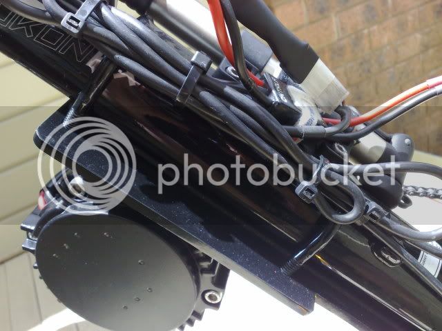
I could make the lower curved aluminum pieces relatively thin walled (maybe 3 or 4mm) so they could curve themselves to the shape of the frame tube. The area where the bolts pass through at each end of the aluminum clamp could be much thicker and the bolt holes could be ovalled a touch to allow the bolt head area of the mount to change angle slightly with varying tube diameters.
How about that?
Matt
That sounds like a really great idea! Is it going to be subject to flexing? If so would stainless steel be a better choice?
If provide a solution that works well for different sizes of round tubes and odd frame shapes like D's Kona it is a major accomplishment. This should do that
and could probably be made to work with really odd frame shapes like Gary's Dahon's.