High power RC motor and drive unit production

Hi,

recumpence said:
This drive could be made more adjustable, or more compact, or more economical, or higher power handling, or more efficient, but not all of the above. I want to get the first run of drives out there to gauge response to their design and performance, then make a second run with (potentially) higher production numbers and any changes that seem needed or useful.
Matt

Because space for mounting is going to be a premium with most bikes I would think the possibility of a more compact form factor is the most important on that list.

I think the most important factors required to get a good result with this drive are solid mounting and a good chain line. So anything you can provide to make mounting easier would be very useful. Then once its mounted the ability to tweak the shaft or sprockets to get a perfect chain line seems crucial.

recumpence said:
There are just so many options on projects like this. I could make changes on my designs forever. At some point I just need to buckle down and settle on a design. That is what I did here. But, since setting on this design, I have not come up with any improvements. So, at least here in the idea stage, the design has evolved pretty far.

But I'm sure it will be great as is so relax and have some fun :)

Hangdog98 said:
Has anybody tested the NuVinci hub over a decent time frame? It uses some special oil to provide friction between rotating balls and a drive plates and I wonder if it has actually met the torque claims made by the manufacturer. We were supposed to get one from NuVinci to test on our cargo bike but the deal vaporized and the rep never returned our emails. I worry about that stuff when committing to a design. A Rohloff would be the Shizzle though, too bad it's so expensive.

Of the remaining big brands, Shimano, Sturmey and SRAM, I think it comes down to spares and service availability. I read today that Shimano was having trouble with OEM Alfine hubs fitted to Giant CRX bikes because, Shimano claims, the sprocket was incorrectly fitted at the factory. Hmmmm... maybe I should stick with the Nexus red band. Tried and tested.

I think the Nuvinci is very strong (and heavy). If you want to try one this is a good price (of course I'm biased :) ):
http://endless-sphere.com/forums/viewtopic.php?f=9&t=7388
Nuvinci Hubs - $275 each! (includes shipping in the U.S)

Gary knows someone who uses an Etek with Nexus 3 speed (68 mph in 1st gear) and 7 speed hubs without problems.

You might be interested in this review of geared hubs:
http://www.velovision.com/mag/issue29/vv29hubgears.pdf
 
not that i know anything about using a nuvinci but for those who are interested our member "bikeraider" used the bicycle version of the nuvinci without much sucess, i think he was using an etek r and the nuvinci didn't work well at all - check out his build for more info.
Agree with Mitch that compactness is a main aspect but that said robustness is top of my list and i wouldn't want to comprimise any of the aspects matt lists to make it more compact.
i'm really looking forward to seeing the finished drive, once there's some fully assembled pics it will become easier to understand how it works and how i'll mount.
Bash them out Matt, we can work on asthetics later on :)


Cheers,

D
 
When I said the drive was adjustable, I neglected to mention that chain line is very easy to adjust as well. When you see the drive, you will understand.

I actually designed the drive to be as compact as possible, within reason. The secondary drive is about 3/4 inch longer than needed for mose applications. That was done to accomodate a very low ratio for that stage if needed. The first stage is pretty compact. Also, depending on the ratio, the first stage main plate can be shortened very easily.

Its all good. My recumbent drive is a bit more compact (about 20% more compact) because it has a maximum reduction capability of roughly 7 to 1. The production drive can almost achieve that in the first stage alone. :D

Also, mounting is somewhat adjustable too. Not only is mounting adjustable, there are two completely different methods that can be used to mount the drive.

This drive is also modular. Any future revisions will be reverse compatible. So, (as far as I can see) any future updates should be directly compatible with the vesrion 1 drive. That way, they can be updated if needed/wanted.

Matt
 
sweeeeeeet.
i'll get her running first then look at some anodising black 8)
good news on the chainline Matt that's awesome.woohoooo it's going to be a monster summer.

Cheers,

D
 
A place where you can get a variety of timing sprockets and belts is Stock Drive Products http://www.sdp-si.com I’ve ordered from them several times. If you are ordering to Canada unfortunately they only ship by courier (huge brokerage fees) so you best make it worthwhile.
 
My "secret" application for Matt's belt/chain drive unit is a folding platform scooter...so space is definitely at a premium there.

My other plans were to also use a drive unit on my Bachetta Giro, but I got a bit impatient and ended up engineering & machining my own setup in one evening (inspired by Matt's drive units); info to be posted here by the end of this weekend...I'm just plain tired this evening...but if you're impatient, keep an eye on http://gregg.berkholtz.net/vehicles/
 
Stock Drive is where I get the majority of my drive component blanks. Then I machine them for weight savings. Great place to deal with. :D

If all goes well with my drive, I can look into a scaled down version for lower power setups as well. It is amazing how small a drive can be with a sub 1000 watt rating.

Anyway, the project trudges on!

Matt
 
Here is a quick sketch of the drive unit.

You can see how it can be layed out or folded up, or any position in between.

The shaft centers are 3 and 1/2 inches apart for the secondary drive and the motor is mounted on a slotted plate for belt tension adjustment.

There will be various mounting tabs for it that are not shown. But, this gives you an idea of the actual drive. This was drawn on 1/4 inch square graph paper at roughly 1/2 scale.

I included the same picture I showed of some finished parts before. You can see by comparing the drawing to the picture, how it will look. Bear in mind, the photograph shows very large pulley and sprocket. These are the absolute maximum size for a very drastic reduction ratio. Most drives would use much smaller pulleys and sprockets.

Any questions?

Matt
 

Attachments

  • sketch1.jpg
    239.2 KB · Views: 2,114
  • drive5.jpg
    144.6 KB · Views: 2,074
Okay, I finally get it now. :roll:

For a single stage version, would you just use the motor plate, with the one tube end to hold the larger sprocket and the output shaft? For the smaller #25 sprocket, that would normally go on the primary shaft, what is the bore? Does it have a set screw? My motor/GB has a 14mm output shaft.

-- Gary
 
Yes, that is correct.

The single stage would use one tube with bearings pressed in place. The mechanical tube is 1 and 1/8 inch bore.

Your 14mm shaft motor should not be a problem. I should be able to bore a #25 sprocket to 14mm. It would use a set screw, not a keyway, though.

Matt
 
Hi Matt,

slight side issue here but do you know the kv rating of the pletty terminator?
if not do you know the rpm i would get at 50.4v?
i've looked for it myself but i cant find it and i cant seem to work it out from the table on the icarerc site? seems you can't just multiply up from the stated voltages as it varies.
oh sorry one more thing - the pulley and sprocket in the picture, how many teeth on each? and is the sprocket #25 pitch?
what will the teeth be on the small #25 sprocket?
what will be the amount of teeth on the motor pulley too?
what sort of final sprocket will you use? is it a normal freewheel?
lol, is that enough questions? ;p
sorry for all the questions Matt but i'm trying to work out exactly what i need :roll:

Cheers Matt,

D
 
The Terminator is 200 KV if I remember correctly (if I am wrong, it is very close to that).

I can tell you my recumbent is geared 4.5 or 5 to 1 in the drive unit and another 3 to 1 to the wheel. So, I have about 14 or 15 to 1 from the motor to the rear wheel. This is running 40 volts (50.4 fully charged) and gives me 41mph top speed. So, if you want 20mph, you will need 26 to 28 to 1 to the rear wheel. Or, for 30mph, you would need roughly 20 to 1 from the motor to the wheel.

The drive is pretty wide open as far as how it can be setup. What I am really leaning toward is a standard freewheel on the output shaft. That is because I am having a hard time finding info related to running a oneway bearing on the shaft as a freewheel. Typical freewheel adaptors are for 5/8 inch shafts. My output shaft is 1/2 inch. So, I could either use a shim to couple them together, or have my own freewheel adaptors made for 1/2 inch bore. I have never had any work like that performed for me, so I will have to look into it. But, I am sure it will work out.

I am innitially making 50 tooth (5mm pitch) main pullies and 60 tooth (the one in the pic is a large 70 tooth). I can get any tooth size for custom setups, though.

What are your thoughts on the layout?

Matt
 
recumpence said:
Yes, that is correct.

The single stage would use one tube with bearings pressed in place. The mechanical tube is 1 and 1/8 inch bore.

Your 14mm shaft motor should not be a problem. I should be able to bore a #25 sprocket to 14mm. It would use a set screw, not a keyway, though.

Matt

A set screw would be perfect. The shaft has a keyway, but obviously the set screw can use this in place of a "flat", like we do with the helis.
 
Hi Matt,Gary,

you lost me a little there - the shaft is keyed and the sprockets have grub screws that lock down in the keyway as opposed to a key? is that right?
Thanks for that information Matt that helps me do the math some more.
i have to work all that out so i understand it well :oops: , as far as my goal is concerned, im trying to figure out exactly what i need in terms of reduction but before i do that i have to understand if there are any diferences in performance that depend on how you reduce the speed? lets say i had to get 10-1 (i wish) and i had single reduction, would there be any difference in having say 5-1 then 2-1 to the wheel (multiply right??) as opposed to having say 2.5-1 first stage and then 4-1? if that makes any sense at all lol.
if it doesn't make any difference that would mean i could juggle them some until i get the sizes right for the mounting i want, but there must be minimums to pulleys i guess due to purchase issues?
the layout you have is impressive matt and i think lots of people will be able to use it with no mods, but i think mine will need wayy modding though (read custom build).I would want a much more compact unit somewhere in the region of 2.5" square :shock: but that said i would want the flexibility of this drive too - easy customer huh?
do you think its possible to reduce the pletty enough for say 30mph within those restrictions ?
this is definately the answer for my build i just need to tweak it slightly :twisted:
btw do we know that has used the astroflight throttle on the forum? i need to check that i can use it or,and preferred,use a standard xlyte 5k throttle?


Cheers,

D
 
recumpence said:
The Terminator is 200 KV if I remember correctly (if I am wrong, it is very close to that).

I can tell you my recumbent is geared 4.5 or 5 to 1 in the drive unit and another 3 to 1 to the wheel. So, I have about 14 or 15 to 1 from the motor to the rear wheel. This is running 40 volts (50.4 fully charged) and gives me 41mph top speed. So, if you want 20mph, you will need 26 to 28 to 1 to the rear wheel. Or, for 30mph, you would need roughly 20 to 1 from the motor to the wheel.

The drive is pretty wide open as far as how it can be setup. What I am really leaning toward is a standard freewheel on the output shaft. That is because I am having a hard time finding info related to running a oneway bearing on the shaft as a freewheel. Typical freewheel adaptors are for 5/8 inch shafts. My output shaft is 1/2 inch. So, I could either use a shim to couple them together, or have my own freewheel adaptors made for 1/2 inch bore. I have never had any work like that performed for me, so I will have to look into it. But, I am sure it will work out.

I am innitially making 50 tooth (5mm pitch) main pullies and 60 tooth (the one in the pic is a large 70 tooth). I can get any tooth size for custom setups, though.

What are your thoughts on the layout?

Matt

With the "mid-drive" series setup that Mitch and I are doing, the output shaft needs a oneway on the large #25 sprocket. We also need a freewheel that will drive crankset will drive, and finally a fixed sprocket to drive the rear hub. We are having a hard time finding these 5/8' freewheel adapters. This one is for a trike setup, and is 15mm. Mitch also found this one and although it is 5/8", it is designed to use a keyway, so it doesn't have a set screw. Do you have another source for these?

-- Gary
 
deecanio said:
Hi Matt,Gary,

you lost me a little there - the shaft is keyed and the sprockets have grub screws that lock down in the keyway as opposed to a key? is that right?
Thanks for that information Matt that helps me do the math some more.
i have to work all that out so i understand it well :oops: , as far as my goal is concerned, im trying to figure out exactly what i need in terms of reduction but before i do that i have to understand if there are any diferences in performance that depend on how you reduce the speed? lets say i had to get 10-1 (i wish) and i had single reduction, would there be any difference in having say 5-1 then 2-1 to the wheel (multiply right??) as opposed to having say 2.5-1 first stage and then 4-1? if that makes any sense at all lol.
if it doesn't make any difference that would mean i could juggle them some until i get the sizes right for the mounting i want, but there must be minimums to pulleys i guess due to purchase issues?
the layout you have is impressive matt and i think lots of people will be able to use it with no mods, but i think mine will need wayy modding though (read custom build).I would want a much more compact unit somewhere in the region of 2.5" square :shock: but that said i would want the flexibility of this drive too - easy customer huh?
do you think its possible to reduce the pletty enough for say 30mph within those restrictions ?
this is definately the answer for my build i just need to tweak it slightly :twisted:
btw do we know that has used the astroflight throttle on the forum? i need to check that i can use it or,and preferred,use a standard xlyte 5k throttle?


Cheers,

D

Yes, the set screw would lock onto the keyway slot. When we use these motors on helicopters we usually have to grind a flat spot on the motor shaft, in order to give the set screw soethig to lock onto.

Regarding your gearing issue, a single drive generally will have less losses to deal with, but one advantage of splitting the reduction into two stages is that the smaller sprockets/pullies can be larger, so that more teeth can be engaged.

By my calculations, running a 200 kV motor at roughly 50V will spin it at around 8500 rpm. Reducing that by a combined 20:1 will give you a top speed withe a 26"tire of about 34 mph. Doing that with a 4:1 and a 5:1 reduction for the two stages would keep things fairly compact, but I'm not sure it is possible to get to 2.5" square, no matter what you use.

-- Gary
 
D,

The keyed shaft Gary and I are talking about is for his unique planetary reduction 14mm output shaft. There are no keyway slots used with my drive.

Gary is correct, 2.5 inches square is pretty much impossible.

Oh, also, I just realized my reduction drive drawings are off a bit. The motor plate shows (in the sketch) to be 7 inches long. That is not correct. The motor plate will only be 5.5 inches long. This drive is actually only a tiny bit bigger than my recumbent reduction unit. :)

At any rate, I am ready to make some custom stuff, assuming it is within reason. Custom ratios, for instance, is not a problem. It is not a huge deal to special order different pulleys and sprockets.

Matt
 
Hi,

recumpence said:
When I said the drive was adjustable, I neglected to mention that chain line is very easy to adjust as well. When you see the drive, you will understand.

It took me a month after the initial design was posted to realize that this is important but Matt had it nailed in the initial design!

recumpence said:
Here is a quick sketch of the drive unit.

You can see how it can be layed out or folded up, or any position in between.

What are your thoughts on the layout?

I think its awesome! Very strong. Very compact (except length which is a basic reduction vs number of teeth issue). Bends in the middle. The price is very reasonable. Could you add an attachment to make toast or tea (for the UK :) )?

recumpence said:
What I am really leaning toward is a standard freewheel on the output shaft. That is because I am having a hard time finding info related to running a oneway bearing on the shaft as a freewheel. Typical freewheel adaptors are for 5/8 inch shafts. My output shaft is 1/2 inch. So, I could either use a shim to couple them together, or have my own freewheel adaptors made for 1/2 inch bore.

I like the FW idea. I believe they are stronger. You previously mentioned using sleeves welded to the shaft to adapt it to 5/8" for use with FW adaptors. Another possibility would be slotting the sleeve so its shaped like a "C" (for use with keyed FW adaptors) or drilling hole(s) in the sleeve (for use with set keyed) adaptors. If the set key or key is connected to the shaft the sleeves would not need to be fastened to either the shaft or the adaptor

The Staton Adaptor (uses a key) is for a 5/8" shaft. The miami sun (uses set screws) is for a 15mm shaft. Someone on this forum had two custom made for $70 each. Some one else had 100 made (3/4" shaft with key and set screws) for about $12 apiece and is selling them:
http://forum.atomiczombie.com/showthread.php?t=135
It's an adapter to use a standard BMX freewheel on a 3/4" shaft, with a standard domestic 3/16 key. We use them a lot in Kinetic Sculpture Racing -- often hand-made one-at-the-time.

If this part looks familiar, it's because it does exist -- sort of. It is available for 5/8 " shaft, and for 15 MM shaft, from the big bike part distributor J&B Importers. Most commonly, they are used on adult tricycles, the Miami Sun, the RhodesCar, and such machines. But they have not to my knowledge existed for 3/4 " shaft -- until I had 100 of them made to order.

For those 100, I paid $1276,-. When I pass them along, I include a set screw and a key with each. Then I put it in a JiffyBag and mail it to you. Then I ask to be reimbursed $20,- for the first one and $15,- for additional pieces.

GGoodrum said:
With the "mid-drive" series setup that Mitch and I are doing, the output shaft needs a oneway on the large #25 sprocket. We also need a freewheel that will drive crankset will drive, and finally a fixed sprocket to drive the rear hub. We are having a hard time finding these 5/8' freewheel adapters. Do you have another source for these?

-- Gary

A FW on the input side of the final shaft would work just as well (or maybe better) than a oneway.

We can use a FW adaptor for the Crank Driven FW. We can also use a FW adaptor to mount one of these cogs on the shaft.

imgDsp.aspx


Because the crank drives the sprocket the second FW adaptor needs to be flipped. A potential problem is the sprockets would be about .4" apart plus the twice width of the shoulder of the FW adaptors. If the shoulder is too wide it might be hard to get good chainlines to both the crank and rear hubs. Does anyone know the thickness of the shoulders on the Staton FW adaptors?
 
With the "mid-drive" series setup that Mitch and I are doing, the output shaft needs a oneway on the large #25 sprocket. We also need a freewheel that will drive crankset will drive, and finally a fixed sprocket to drive the rear hub. We are having a hard time finding these 5/8' freewheel adapters. This one is for a trike setup, and is 15mm. Mitch also found this one and although it is 5/8", it is designed to use a keyway, so it doesn't have a set screw. Do you have another source for these?

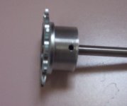
Hello, I made a freewheel adapter recently while working on some gearbox design ideas. I used 6061 aluminum though it looks like the ones you've posted links for are steel. I don't have a lathe (yet) so I bought a 1-3/8 die and threaded an aluminum rod and used a center finder tool from micro mark and drilled the shaft bore with a drill press.Then drilled and tapped in a 10/32 set screw.I Haven't tested it yet but there is no visible wobble when I spin it in some bearings.Here's a pic, theres a track cog on there now but its the same threads as a freewheel. I'd offer to make you one but I don't have a way to cut a 5/8 inch hole I would order a carbide tipped hole saw for that probably.adapter.jpg
 
mud2005 said:
Hello, I made a freewheel adapter recently while working on some gearbox design ideas. I used 6061 aluminum though it looks like the ones you've posted links for are steel. I don't have a lathe (yet) so I bought a 1-3/8 die and threaded an aluminum rod and used a center finder tool from micro mark and drilled the shaft bore with a drill press.Then drilled and tapped in a 10/32 set screw.I Haven't tested it yet but there is no visible wobble when I spin it in some bearings.Here's a pic, theres a track cog on there now but its the same threads as a freewheel. I'd offer to make you one but I don't have a way to cut a 5/8 inch hole I would order a carbide tipped hole saw for that probably.

The perfect FW adaptor for this application would be for a 1/2" shaft. The reason 5/8" is mentioned is that Matt has some sleeve material that can be put on the 1/2" shaft to bring it up to 5/8".

When the drive design (v1.0 :) ) is finalized we'll keep your offer in mind. Thanks!
 
The perfect FW adaptor for this application would be for a 1/2" shaft. The reason 5/8" is mentioned is that Matt has some sleeve material that can be put on the 1/2" shaft to bring it up to 5/8".

cool, 1/2 inch is no problem :)
 
Sure, here's where I got the die: victornet.com and I got the die stock here: mscdirect.com

I quickly discovered its impossible to use a die that large without some kind of guide to keep the aluminum at the right angle while starting the threading process. I got some solid oak 3x3's and a 1-3/8 forstner bit and made this guideView attachment 1
I used a strap wrench to turn the aluminum in the die but it ended up breaking, so get yourself a heavy duty strap wrench if you can.
Also look into micro mark for the tools to find the center of a piece easily and they also have a guide to make it easy to find the center when drilling the set screw hole.
If this sounds like a PITA then email me and Ill make you one :) stub2005@gmail.com
oh yeah, don't forget cutting oil on the die it really helps
 
Back
Top