How to find the magnetic flux shape?

Joined
Apr 25, 2014
Messages
3,088
Location
Sausalito
Is there a program where you can simulate a motors construction and alter the back iron shape to add a groove behind a magnet?

the way the lines of flux travel it seems there's a gap behind the magnet where the back iron isn't necessary and I'm trying to find exactly how big this shape is for my 25x9x3 magnets. Typically a backiron need only be about half as thick as the magnets to get 99 percent of the flux but I want to do it thinner directly behind the magnets and hoping to not lose flux. The groove is 12mm wide and then the thickness goes up to 2.5mm and more than enough.
 
I'm having trouble running FEMM and emetor doesn't seem to have the ability to adjust the back iron shape.

what do you think of this pic:

Motor section magnet view.JPG

the white ring is the back iron. the yellow is not related. in the pic it's 2.65mm mags but should find out tonight if it'll be too long to wait for 3mm curved, which I'd rather.
this is the fall back plan design but I'd like to find out if I cut the whole inside diameter a bit wider, so instead of 54mm, as in this picture, it would be cut to 54.6mm ID. so the back iron is thinner by .3mm everywhere. the OD is 59mm which is good as the can is made with .2% carbon content (mild steel), but the grooves behind the magnets shrink down to about .7mm. This would be really bad if the whole back iron were only this thick but I'm hoping, and trying to find out, if that space behind the magnets is inconsequential for the flux.

hoping a motor do-gooder will throw me a bone. I'm planning on deciding this tonight one way or the other. either a bit heavier and safer or lighter if I can be assured it'll get me the same flux return or very close.
 
Hummina Shadeeba said:
I'm having trouble running FEMM and emetor doesn't seem to have the ability to adjust the back iron shape.

what do you think of this pic:

View attachment 1

the white ring is the back iron. the yellow is not related. in the pic it's 2.65mm mags but should find out tonight if it'll be too long to wait for 3mm curved, which I'd rather.
this is the fall back plan design but I'd like to find out if I cut the whole inside diameter a bit wider, so instead of 54mm, as in this picture, it would be cut to 54.6mm ID. so the back iron is thinner by .3mm everywhere. the OD is 59mm which is good as the can is made with 1020 steel (mild steel), but the grooves behind the magnets shrink down to about .7mm. This would be really bad if the whole back iron were only this thick but I'm hoping, and trying to find out, if that space behind the magnets is inconsequential for the flux.

hoping a motor do-gooder will throw me a bone. I'm planning on deciding this tonight one way or the other. either a bit heavier and safer or lighter if I can be assured it'll get me the same flux return or very close.


image.png
And I'm somewhat assuming even this design with the back iron from 54 to 59mm but with the groove leaving only one mm behind the magnets.
My beliefs are based largely and this :
J Magnetics - Steel Plate Thickness Calculator
And what seems to be he shape of flux paths

The motors I'm getting made in China and offering everyone on es at manufacturing cost , hoping we get to 100 motors to get the bulk price of 64.40. Skateboard hubmotor.
 
The shapes are extremely important of the magnet to tooth profile interaction. If not done well, the motor will perform poorly and be loud and poor efficiency.

Fortunately it can be simulated, but its non-trivial. ES members Biff or Farfle or Miles are experts in getting these shapes correct, I would not just guess.

Also, excited for cheap skate hubmotors! Thank you!
 
The magnet-to-tooth profile, while maybe important ( although I've seen hub motors built with old copy machine stators with 100% fill with good results), it isn't my pressing concern. Tonight I'm trying to find out if the groove that will be in every magnet's back iron will avoid cutting flux lines. Im giving it one more hour and after that I'm throwing in the credit card and getting samples made with the thicker can as in the picture. It seems every outrunner I come across is leaking a huge amount of flux anyway and still going, not that I want that but with the thicker can I'm feeling safer. I'd love to hear from one of the names you mentioned to confirm not much flux will be lost..but based on the little I know and pictures of flux in steel I'm feeling confident enough to gamble a bit. Not enough to go for the thinner can though
 
H.S.

From your picture, the changes from your scalloping are unlikely to affect the performance. The area of highest flux density will be between the magnets and you'd need to use FEMM to assess that.
 
Would you say going with the even thinner can, at 54.6 ID and 59 OD would be too thin with the scallops? The thinnest part at the center of the scallop would be .7mm. 1020 steel. Thanks for your help
Miles.
 
Hummina Shadeeba said:
Would you say going with the even thinner can, at 54.6 ID and 59 OD would be too thin with the scallops? The thinnest part at the center of the scallop would be .7mm. 1020 steel.
Well, there are two issues.... Reducing the overall can thickness, will increase the maximum flux density, that's nothing to do with the scalloping, though. The other issue is the structural integrity......
 
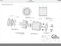
Structurally I think we're fine with the thinner can there's a lot more to the ends that isn't shown. If u look at the exploded drawing you can see. In my simplified understanding I just need to have the can thick enough where the flux lines are going..otherwise bad news. Simplified. I feel if I just were to simulate one magnet with the scallop behind it if be good. Maybe it's more complicated.
Tell me in your best educated accent what you recommend please. I'm too impatient to go deeper into it at this point than asking for help from someone who knows
 
Hummina Shadeeba said:
Simplified. I feel if I just were to simulate one magnet with the scallop behind it if be good. Maybe it's more complicated.
Tell me in your best educated accent what you recommend please. I'm too impatient to go deeper into it at this point than asking for help from someone who knows

No, you need to model the complete magnetic circuit.

Stick with the thicker version.
 
They put the magnets beside the scallop in the back. Perfectly opposite of what I wanted. I haven't had the chance to run them yet as waiting for esc in a day. but they did send me a video of them going wonderfully smooth and quietly. Maybe I'll figure out thr program and see what's going on. Got them yesterday.
The magnetic strength outside the can is small. a steel nut pulls much stronger towards a typical 63mm Out Runner. I like that. I don't know why I like that other then strong magnetic field = good.


Ican run one motor as a generator and spin the second motor easily. Never done that before.
 

Attachments

  • image.jpeg
    image.jpeg
    77.4 KB · Views: 946
  • image.jpg
    image.jpg
    85.8 KB · Views: 946
  • image.jpeg
    image.jpeg
    95.4 KB · Views: 627
Back
Top