rkosiorek
100 kW
lately i am finding it more necessary to measure milliOhm values to check motor windings and controller shunt resistors. so i have decided to build an adapter to allow me to use my regular Multimeter to measure and resolve 0.001 ohm.
the oldest form of ohmmeter would put a known Current through the unknown resistance and measure the voltage dropped by that resistance. Ohms law dictated the resistor value as R=E/I
now if i use a 1A constant current source and i measure the voltage drop the resistance would be R=E/1A or R=E. As long as my meter can resolve 1 milliVolt i can measure 1milliOhm.
one of the common IC Regulators can be used as a precision current source. the regulator works by adjusting itself so that there is always a 1.25V difference between the output and a reference pin. if i put a 1.25Ohm resistor there the current would be 1.25V/1.25R = 1A. but then my meter would only be as accurate as my resistors. which could be not accurate at all.
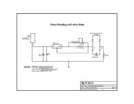
so i made my resistor variable so i could calibrate the value. that is why i have a resistor network making up the 1.25R resistor. i picked 1.3R because it was the next size larger than 1.25R. by calculation i established that i would need a 32R resistor in parallel with the 1.3r to make 1.25R. ths closest variable resistor would be 50R. i also wanted to make sure that i could not short out the output to the reference pin and toast the regulator. so i put a 7.5R in series with the variable resistor. i picked 7.5R becasue if i adjusted the 50R variable to the center it would be 25R add that to the 7.5R and i would have the 32R that i would need for the total resistance to add up to 1.25R.
i also added the 2R at R3 for the same reason. i did not want to stress anything by preventing a dead short.
i got a 5V 1A power supply for $2.00 from the Salvation Army thrift shop. the other parts i got from my junk drawer except for the 50R potentiometer. i had to buy that and as long as i was buying that i bought a plastic box and some binding posts to put it in.
Here is the schematic:

so to use it you plug in the wall adapter, and hook up the meter. switch it to read amps. calibrate the meter by adjusting the variable resistor until the meter just reads 1A. now switch the meter to it's lowest DC Voltage range, usually 200mV.
measure your unknown resistor by hooking it up to TP1 and TP2. read your value in milliOhms directly off of the meter. it will be as acurate as your meter is.
rick
the oldest form of ohmmeter would put a known Current through the unknown resistance and measure the voltage dropped by that resistance. Ohms law dictated the resistor value as R=E/I
now if i use a 1A constant current source and i measure the voltage drop the resistance would be R=E/1A or R=E. As long as my meter can resolve 1 milliVolt i can measure 1milliOhm.
one of the common IC Regulators can be used as a precision current source. the regulator works by adjusting itself so that there is always a 1.25V difference between the output and a reference pin. if i put a 1.25Ohm resistor there the current would be 1.25V/1.25R = 1A. but then my meter would only be as accurate as my resistors. which could be not accurate at all.
so i made my resistor variable so i could calibrate the value. that is why i have a resistor network making up the 1.25R resistor. i picked 1.3R because it was the next size larger than 1.25R. by calculation i established that i would need a 32R resistor in parallel with the 1.3r to make 1.25R. ths closest variable resistor would be 50R. i also wanted to make sure that i could not short out the output to the reference pin and toast the regulator. so i put a 7.5R in series with the variable resistor. i picked 7.5R becasue if i adjusted the 50R variable to the center it would be 25R add that to the 7.5R and i would have the 32R that i would need for the total resistance to add up to 1.25R.
i also added the 2R at R3 for the same reason. i did not want to stress anything by preventing a dead short.
i got a 5V 1A power supply for $2.00 from the Salvation Army thrift shop. the other parts i got from my junk drawer except for the 50R potentiometer. i had to buy that and as long as i was buying that i bought a plastic box and some binding posts to put it in.
Here is the schematic:

so to use it you plug in the wall adapter, and hook up the meter. switch it to read amps. calibrate the meter by adjusting the variable resistor until the meter just reads 1A. now switch the meter to it's lowest DC Voltage range, usually 200mV.
measure your unknown resistor by hooking it up to TP1 and TP2. read your value in milliOhms directly off of the meter. it will be as acurate as your meter is.
rick

