bjorken
1 µW
A while back, I experienced an axle spinout followed by my motor refusing to function and throwing an "Error 24" on the HUD. After many google and youtube searches, I was able to disassemble the hub motor but I'm now stumped on what to do next. Based on the error I assumed that either one or more of the hall sensors needed replacing, or perhaps the whole motor cable had gotten twisted (despite visual evidence of this) and would need to get swapped. So far so good.
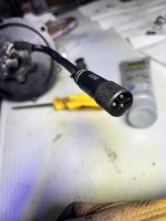
The issue I am having now is that I can't figure out how to test the Hall sensors given the configuration of my motor and cable. I.e. the cable comes out of the motor as pictured below, and terminates in a male 3-pin connector. That connection leads directly into the hub controller, so there's no opportunity to isolate individual hall sensor or phase wires for testing with multimeter. The second picture below shows all the wires coming OUT of the controller box, and these don't seem to be continuous with the solder points on the hub PCB itself (but I'm not sure if they should be) since they aren't directly connected to the wire coming into the controller.
I also have one of those cheap ebikle testers, in case that helps. I just can't figure out how to hook it up given the above, same as multimeter.
My questions are:
1) Would anyone suggest a different approach? Am I barking up the wrong tree?
2) Assuming no, is the best next step to crack open the controller box and locate where the incoming cable's wires terminate on the PCB there and test for continuity with hub PCB?
Any help would be much appreciated!
 View attachment 2025-03-28 18.35.22.jpg
The issue I am having now is that I can't figure out how to test the Hall sensors given the configuration of my motor and cable. I.e. the cable comes out of the motor as pictured below, and terminates in a male 3-pin connector. That connection leads directly into the hub controller, so there's no opportunity to isolate individual hall sensor or phase wires for testing with multimeter. The second picture below shows all the wires coming OUT of the controller box, and these don't seem to be continuous with the solder points on the hub PCB itself (but I'm not sure if they should be) since they aren't directly connected to the wire coming into the controller.
I also have one of those cheap ebikle testers, in case that helps. I just can't figure out how to hook it up given the above, same as multimeter.
My questions are:
1) Would anyone suggest a different approach? Am I barking up the wrong tree?
2) Assuming no, is the best next step to crack open the controller box and locate where the incoming cable's wires terminate on the PCB there and test for continuity with hub PCB?
Any help would be much appreciated!
 View attachment 2025-03-28 18.35.22.jpg


