I need help, as i dont have anywhere to ask, and no one to help me

Balmorhea said:
MadRhino said:
What I meant, is that you are showing the simulation for a motor that is not available, in a winding that is more than double the speed, with a controller that is too small for it. That, is not realistic. Even with another similar motor, nobody would power a 26 lbs motor with a 20A controller.

It was a quick illustration of winding by itself multiplying output torque by more than 2X. I picked that motor because it’s one that has a large % variation of winding available in the simulator.

These results do raise the question: Why does a change in winding affect torque more in some cases than in others? Is it the controller multiplying phase current more for a low impedance motor? Torque per amp fed to the motor should vary in more or less direct proportion to the number of turns, given the same copper fill. So when that doesn’t happen, is it only the controller trading amps for volts, or is there something else at work?

The 5302 is not in the simulator, not in the latest version at least, and was never sold by Crystalyte. This was a mod that some had done to double the kv of the 5304. The 5305 had been sold by special group order with the 5306 (of which I got one).

The numbers are from the old simulator, that had mistakes in the results. There are still some, but fewer because a lot of work had been spent to collect true data.
 
Please explain me how i drive this controller on 1450w? https://nexun.pl/czesci-do-e-bike/kt36-48svprc-36-48v-30a-sinus
 
Balmorhea said:
These results do raise the question: Why does a change in winding affect torque more in some cases than in others? Is it the controller multiplying phase current more for a low impedance motor?
So when that doesn’t happen, is it only the controller trading amps for volts, or is there something else at work?

Is there a way to monitor phase current when riding? Would a cheap clamp on current meter work for monitoring phase current, or is there a way to monitor through the controller? Sorry, I like looking at data and the torque discussion is interesting.
 
E-HP said:
Balmorhea said:
These results do raise the question: Why does a change in winding affect torque more in some cases than in others? Is it the controller multiplying phase current more for a low impedance motor?
So when that doesn’t happen, is it only the controller trading amps for volts, or is there something else at work?

Is there a way to monitor phase current when riding? Would a cheap clamp on current meter work for monitoring phase current, or is there a way to monitor through the controller? Sorry, I like looking at data and the torque discussion is interesting.

You should monitor battery current for this, after all it is ‘watt’ the motor does really consume. A clamp Ampmeter does good, if it is rated high enough.
 
Davidcroatia said:
Please explain me how i drive this controller on 1450w? https://nexun.pl/czesci-do-e-bike/kt36-48svprc-36-48v-30a-sinus

Somehow I can’t translate this link into a language that I can read. Yet, if the controller is available with bluetooth, you can set the program with you smartphone.
 
MadRhino said:
E-HP said:
Balmorhea said:
These results do raise the question: Why does a change in winding affect torque more in some cases than in others? Is it the controller multiplying phase current more for a low impedance motor?
So when that doesn’t happen, is it only the controller trading amps for volts, or is there something else at work?

Is there a way to monitor phase current when riding? Would a cheap clamp on current meter work for monitoring phase current, or is there a way to monitor through the controller? Sorry, I like looking at data and the torque discussion is interesting.

You should monitor battery current for this, after all it is ‘watt’ the motor does really consume. A clamp Ampmeter does good, if it is rated high enough.

Right. But if the slow and fast motors are equally efficient, and one is slower, then the same power input will manifest as proportionally more torque. If this isn’t happening, what is?

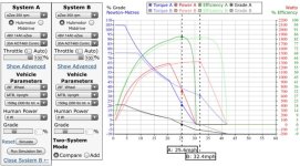
This is the chart for a motor that’s well characterized in the sim. It makes sense to me that the maximum output torque is in approximately inverse proportion to maximum rpm. But they don’t all work like that (at least in the sim), and I’m curious why not?

06632F66-A238-4433-9C5A-238F58E7E3E1.jpeg

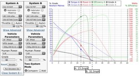
Here’s another chart with all the same parameters set except the choice of motor. But in this case, the difference in max speed is way more the difference in max torque. That shouldn’t happen, because those are the two factors of the power equation. The slow wind makes less power from the same battery and controller and motor architecture, which also doesn’t make sense. So what’s up?

DD616B33-CAF6-4502-AB91-BCC31277B348.jpeg
 
The simulator is getting closer to real life observations, but still renders exaggerated torque to the lower kv motor. The Kv of an electric motor is not a gearing. The copper mass is still the same thus the amplitude of the magnetic field is very similar. The resistance is lower in the fast motor, making it ABLE to consume a lot more current. On the opposite, the higher resistance of a slower motor is making it able to wake up with lesser current, but the power produced is not a direct relation with resistance. Watts are watts no matter what, only the efficiency loss at low speed of the faster motor is making a difference, because watts that are lost cannot produce torque.
 
MadRhino said:
only the efficiency loss at low speed of the faster motor is making a difference, because watts that are lost cannot produce torque.
For equal copper fill, both motors ("fast" and "slow") will have effectively the same efficiency at the same power level and speed. One requires more current and less voltage. The other vice versa. But total power, mag flux, and heat are the same.
 
Now im done, the controller broke down. Im gonna write some stuff please try to answer them, as im gonna order new controller, and i need you to understand.
1. question; i have this controller with kt 3 lcd monitor : kt 36 48 svprcl 30a , the seller that sold it to me said to me to program it like this
lim 70 kmh,dim 26, unt0, p1 46, p2 0, p3 1, p4 0 , p5 15, c1 2 , c2 0, c3 8, c4 0, c5 10, c6 3, c7 0, c8 0, c9 0, c10 n, c11 0 , c12 4, c13 2, c14 2 , l1 0, l2 0, l3 1, l4 5. as stated controller has max current of 0amp , nominal power 500w, max power 1600w

did programming hepled with this controller to use constantly 1500w ? controller is here on this link https://nexun.pl/czesci-do-e-bike/kt36-48svprc-36-48v-30a-sinus . im running this controller on qs motor 1000w .

2. would this controller be a good replacement ?? https://nexun.pl/czesci-do-e-bike/kt48svprc-48v-45a-sinus please help me as i really need to continue to work ... btw im using 2 batteries, one is 40amp 48v 24.5ah, and the othher 50amp 48v 20ah.
 
Just to point out how KT "rates" their controllers, and looking at the specs from the links you provided:

existing "30A" controller description:
Max current 30A
Nominal power 500W
Max power 1600W

proposed "45A" controller description:
Nominal power 1500W
Max power 2600W

If the seller is using the same conventions for both descriptions, it's pretty clear that the existing controller is not a 30A controller, but something more like 15A continuous. Hard to read the label, but it looks like the 30A is max, as described, and the continuous rating looks like maybe 15A.

So, if the descriptions follow the same convention, then looking a the nominal power rating, which appears to mean continuous, then the continuous current rating for 1500W nominal may be closer to 30A or maybe less. Can't read the label on this one to confirm.

For comparison, my old KT controller is also rated at 1500W, and "rated" per the description at 40A. The continuous current is 22A, max current is 40A. That said, my old KT controller never got hot pulling 2000W for 10 or 15 minutes at time.
 
Sorry, what would i get more with new version? Withh oldd i go oon 26 inch 48km an hour and 55 km range plus one battery is 40amp bms will it damage the new controller?
 
serious_sam said:
MadRhino said:
only the efficiency loss at low speed of the faster motor is making a difference, because watts that are lost cannot produce torque.
For equal copper fill, both motors ("fast" and "slow") will have effectively the same efficiency at the same power level and speed. One requires more current and less voltage. The other vice versa. But total power, mag flux, and heat are the same.

Does this assume that both motors have the same resistance?
 
E-HP said:
serious_sam said:
For equal copper fill, both motors ("fast" and "slow") will have effectively the same efficiency at the same power level and speed. One requires more current and less voltage. The other vice versa. But total power, mag flux, and heat are the same.

Does this assume that both motors have the same resistance?

No, it doesn't. It only assumes the same stator geometry and the same weight of copper. The high turn count motor has more resistance due to reduced wire cross-section and increased wire length. But this is completely offset by the reduced current necessary, and the fact that resistance power losses scale as current squared.
 
Balmorhea said:
E-HP said:
serious_sam said:
For equal copper fill, both motors ("fast" and "slow") will have effectively the same efficiency at the same power level and speed. One requires more current and less voltage. The other vice versa. But total power, mag flux, and heat are the same.

Does this assume that both motors have the same resistance?

No, it doesn't. It only assumes the same stator geometry and the same weight of copper. The high turn count motor has more resistance due to reduced wire cross-section and increased wire length. But this is completely offset by the reduced current necessary, and the fact that resistance power losses scale as current squared.

"But total power, mag flux, and heat are the same."

Interesting. So the lower current and higher resistance of the low KV motor is equal to the higher current and lower resistance of the high KV motor, when the same power is applied to the two motors with equal copper fill?
 
E-HP said:
Interesting. So the lower current and higher resistance of the low KV motor is equal to the higher current and lower resistance of the high KV motor, when the same power is applied to the two motors with equal copper fill?
Imagine 2 light bulbs
- Assume each bulb flows 10A @ 10V = 100W each.
- With 2 bulbs in parallel, if you apply 10V then 20A will flow = 200W -> this is analogous to "1T", and is lower resistance.
- With 2 bulbs in series, if you put 20V then 10A will flow = 200W -> this is analogous to "2T", and is higher resistance.
- But see it is exactly the same power input.
- And exactly the same light/heat output.
- And exactly the same efficiency.
- Because the same 2 bulbs are each seeing the same power/current/voltage. They are just wired differently.
- So we conclude 1T=2T (=3T=4T=5T=6T=7T)
- Just different ratio of voltage and current.
- Same basic physics applies to motors (in this example, light is analogous to flux), assuming the same hardware (i.e. the same copper fill and motor structure)
- In the real world, minor differences may include different copper length in end turns, and main phase wire resistance.
- And often different windings do not end up with identical copper fill.
- But this is usually due to manufacturing limitations (i.e. wire diameter and number of strands used per winding not being divisible for all turn counts, etc).
 
Davidcroatia said:
I ordered new controller can you help me how to programm it ? Please :)

What controller did you order?

There's about a hundred different types of ebike controller out there, so you really need to be specific.
 
serious_sam said:
Imagine 2 light bulbs
- Assume each bulb flows 10A @ 10V = 100W each.
- With 2 bulbs in parallel, if you apply 10V then 20A will flow = 200W -> this is analogous to "1T", and is lower resistance.
- With 2 bulbs in series, if you put 20V then 10A will flow = 200W -> this is analogous to "2T", and is higher resistance.
- But see it is exactly the same power input.
- And exactly the same light/heat output.
- And exactly the same efficiency.
- Because the same 2 bulbs are each seeing the same power/current/voltage. They are just wired differently.
- So we conclude 1T=2T (=3T=4T=5T=6T=7T)
- Just different ratio of voltage and current.
- Same basic physics applies to motors (in this example, light is analogous to flux), assuming the same hardware (i.e. the same copper fill and motor structure)
- In the real world, minor differences may include different copper length in end turns, and main phase wire resistance.
- And often different windings do not end up with identical copper fill.
- But this is usually due to manufacturing limitations (i.e. wire diameter and number of strands used per winding not being divisible for all turn counts, etc).

Got it, thanks. The analogy is really helpful for illustrating your point. :thumb:
 
Back
Top