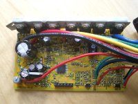
Infineon 6 Fet

Joined
May 28, 2008
Messages
718
Does U2 need a jumper between pin 2 & 3? This is counting left to right.

I got a Infineon 6 Fet from Methods. Everything has been installed, but it doesn't work. The 5 volt regulator (L7805) doesn't seem to be getting power from VCC-L. If I follow the traces from VCC-L, through the 330 ohm resistor, to the regulator it looks like they go through U2, which is not populated. My eyes are not all that good and I may be missing something, so I am just trying to confirm that I need the jumper.

Bubba
 
You shouldn't need to jumper anything that you received from methods, they should be ready to go.

Are you providing power to both the main lead and the turn on lead? (not even sure Methods delivers with these turn on leads in place)?

Just shoot him an email, he will respond quickly ... always has for me and I'm not a customer = )

Do not put a jumper on any of the pads marked U1, U2, etc... these are for IC chips and not for jumpers...the pads which allow jumpers are documented throught this forum on multiple threads (even one I am workign on for the 9FET version).

-Mike
 
U1 is the 5 volt voltage regulator. What is populated in U2?

I will send a PM to Methods. The post is so the info will get out to everybody.

Bubba
 
the current to the 7805 comes from the 12V rail which is the output of the LM317T. nobody can really answer these questions without a picture of where U1 and U2 are anyway. we both have some idea of what's there from working on them, but i can't tell what the spot is you are talking about.
 
Here is a picture of the board. I think that the component numbers are the same on the boards. I don't have a 12 V reg on my board.


Bubba
 
Here is a picture of the programming cable that came with the controller. Does it have the level shifting circuit built in?


Bubba

P1010037.JPG
 
dontsendbubbamail said:
Here is a picture of the programming cable that came with the controller. Does it have the level shifting circuit built in?


Bubba


Yes. That cable is ready to go.
All you have to do is plug it into your PC, start the software, load up the settings, press GO, then poke that connector into the programming slot.
You will see the progress bar go.

Errrr... Wait !
Depends on what chip that slow start is running.
The slow start 18 fet boards ended up not having flash memory so we could not program them.
If there is a potentiometer soldered to the bottom of the board it can not be programmed.

And... that is why I dont do business with Keywin anymore...
He is so happy to sell you programmers for controllers that cant be programmed :roll:

-methods
 
totally different board from the 9 FET infineon. does look like the LM317T should be there at U2, but you gotta follow the trace from the input resistor, there is a 620 ohm resistor as a shunt across the LM317T also on the 9 FET board, look for that too.
 
dontsendbubbamail said:
Here is a picture of the board. I think that the component numbers are the same on the boards. I don't have a 12 V reg on my board.
Bubba

I never even got to look at the 6 fet boards.
I only had 2 of them and (as you recall) I sold them off as soon as I found out that they were slow start.
Looking at the 18 fet slow start boards - they dont use an LM317T - they use the Ghetto-Pulse method.
I wanted to pull whatever you needed and send it to you but no dice.

LM317 is very common and very cheap.
If the board is missing something I will procure it and ship it to you.
Sorry for any inconvenience... Keywin screwed me in so many ways that I am still just now figuring out.
On my 18 fet fast start boards he forgot to populate the diodes :roll:

If it ends up now working out I will refund your money in full.
Sorry for the frustration you are going through.
If you wasted IRFB4110 mosfets I can ship you 6 of those as replacements for free.

Whatever you want. Just let me know :p

-methods
 
Hmmm I have a bunch of these 18 fet slow start boards sitting around...
I know for a fact that they are populated with everything needed.
They cant be programmed but they do have an LVC pot.

If you want to try one out I will ship it to you for Free-99

-methods
 
methods said:
If the board is missing something I will procure it and ship it to you.

If it ends up now working out I will refund your money in full.
Sorry for the frustration you are going through.
If you wasted IRFB4110 mosfets I can ship you 6 of those as replacements for free.

Whatever you want. Just let me know :p

-methods

stator - Thanks for the U2 part number.

methods - Frustration is just part of the game when you are modifying controllers and using RC stuff. I am very happy with my purchase from you and don't expect you to buy extra parts, give a refund my money or give me a free board. You are a stand up guy.

Let me play around with the 6 Fet for a while. I might get one of the 18 fet boards from you later.

Bubba
 
the LM317T is pretty common, if that is what's missing, just solder one in after mounting it on the heat spreader, doesn't need isolation washers either i bet.

someone may see this and have one laying around and mail it to you. but you should follow the trace to verify it is missing. but sounds like it.

tell methods to send me one of the 18 FETand i'll send you one of my 9 FET, hehehe.
 
dnmun,

those are slow starts right? or just missing diodes? lol, i guess it doesn't matter either way... good trade = )

I must admit that's the first time I have seen the 6 fet version out of it's case... it's so tiny, it's almost RC gear.

-Mike
 
just kidding, nopingbubba is gonna have a new one soldered in quick, if i had a loose one i would mail it to him, easier and cheaper than going to buy one.

what's neat is when i shared off 6 of the SS41 hall sensors, to ben in sidney when he asked on the sphere, i sent them in a regular air mail envelope. cost like 90 cents, and he got them as fast as fed ex from dallas. i had already passed on one ebay special on the LM317s. but i know radio shack has them, of just few items. but i bet they charge $3.99 for 2.
 
Hi Bubba,

not sure if this helps, but here is a photo of my working 6FET board that has an LM317T soldered in.
topView.jpg
But I think we have slightly different versions of the board. Mine arrived two weeks ago and is named
EB206-A-2

Best regards,
Thomas
 
Thanks pictures always help. Dnmun is never going to let me forget my battery fiasco. :wink: I got that little old regulator from Radio Shack. The board is now working.

Now I have a question about the hall effects (SS411A). With the bevel side up + is on the left, - is in the middle and output is on the right. I am not seeing the output change when I slowly turn the motor by hand. This is measuring with a volt meter. Should I see the output go high and low? The hall effect are getting power.

Bubba
 
the individual hall sensor outputs have to be connected to the controller hall sensor leads and the controller powered up. both the red wire and black wire also have to be connected to power up the hall sensors, and when the magnet goes by, the output of the sensor will get pulled down or swing up as it changes state, then swiches again as the next magnet comes along, switching every 120o of the full 360o cycle of the the magnets, which is 2 magnets of opposite polarity side to side. on my goldnmotor i counted 46 magnets, so 23 full 360o cycles. so with 36 spokes the magnets will change the output (23/36)x(120/360)=.213 of the spoke to spoke space. or cycle 5 times from one spoke to the next.

bubba, i am watching some FETs on ebay now, and will ask if the guy will include a LM317T if i win the sale, and can send one to you then.
 
dnmun

Thanks for the thinking about me, but I have already gone to Radio Shack and bought the LM317T I needed. I will wire the hall effects back up and give it another try with everything connected.

Bubbba
 
i figured you would do something quick, double check against the other pictures to be sure you have the capacitor on the 12V bus too, but i think you do because they are mounted for reflow.
 
Dnmun the caps are there. I found combinations of hall effect and motor phases where the motor will run good forward or backwards but none of them start easy. You have to give very very slow throttle to get the motor turning. Once it starts turning, it responds to the throttle correctly. I have tried adjusting the hall effect back and forwards by less the 1/8 " increments, but can not find a position where it will start as expected. I know other people have had success with small motors. Mine is the HXT 80-100 130kv ,it is a 6fet soft start controller and the hall effect are 120 deg apart. My hall effectss have the flat side facing the motor. Liveforphysics has had success with a slow start 18 fet controller.

Any suggestions on how to improve the starting?

Bubba
 
yesterday I fitted an HXT 63-74 motor with SS40A hall sensors following the way Jeremy described
in this forum (I milled out spaces in the slots, and put them with the flat side outwards in 120° distance). It works with the new 6 FET controller. The motor had troubles before starting with an expensive sensorless controller (it only started when I turned it by hand) but now with the e-bike controller the motor starts perfectly.
Thomas
 
dontsendbubbamail said:
Dnmun the caps are there. I found combinations of hall effect and motor phases where the motor will run good forward or backwards but none of them start easy. You have to give very very slow throttle to get the motor turning. Once it starts turning, it responds to the throttle correctly. I have tried adjusting the hall effect back and forwards by less the 1/8 " increments, but can not find a position where it will start as expected. I know other people have had success with small motors. Mine is the HXT 80-100 130kv ,it is a 6fet soft start controller and the hall effect are 120 deg apart. My hall effectss have the flat side facing the motor. Liveforphysics has had success with a slow start 18 fet controller.

Any suggestions on how to improve the starting?

Bubba

Hi Bubba,
Just a though... is your controller shutting down due to lvc are you monitoring the voltage when winding it up or the current limiting is kicking in when cracking the throttle open. I also have one of these 6 fet controllers and I have converted both my motors to use fets ( SS411A ) on the outside with a 60 degree spacing with the center hall flipped over and both motors work a treat ( they are slightly smaller motors than yours ). how many poles have your motor got what is the air gap from motor to hall sensor .

Edit: Have you checked that all 3 sensors switch state with a volt meter if you rotate the motor by hand.
 
Back
Top