Instant Start 18 fet Infineon Boards are here...

Mike1 said:
Disaster, my 18 fet controller blew up. I wasn't even using it at the time. Rode a couple of miles day before yesterday and parked up as usual and put it on charge. Ignition circuit was off but main breaker was left on as it usually is.
Came to use it today and main breaker had tripped and wouldn't reset.

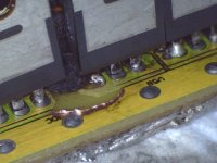
Here's the burnt bit.

This is a view where the B and C phase fets meet, near the large cap C201. As you can see the thick trace from the cap to VCC has melted.
What would have caused this? Shorted electrolytic?

omg is this the first blown 18 mosfet controller???

noooo!!!

I wonder what went wrong with that controller? ..

SHOW US MORE PICS OF THE PCB

-steveo
 
I'm working on more photos.
It's really odd that that particular track melted when the track on the other side of the board (which had been beefed up) was untouched. I can only think that the big capacitor was only connected on the upper side of the board.
 
Hi Mike,
What voltage are you running at ?. Was there any chance that the controller got wet/damp, It doesn't look like a full blown short that has caused that ( from what i can see from the first pic ) If the cap shorted it would have disintegrated with a large bang ( its there any burn marks in the case ) . Have you measured the fets, are they still ok ?.

edit: More pics would be good, Looking at the picture again there do appear to be a bit of splatter and a main area where it came from ( just under left side fet ) has any sm components gone missing from this area .
 
I'm only running 72V so I thought it would be safe to leave the main breaker on during charging.
I'm going to try to clean it up a bit today and post some better pictures. Two phases measured low resistance to VCC before I took it out of the case. I'll check again now I've cleaned off a little of the burnt stuff.
Casing was well sealed, no damp or water in there.
 
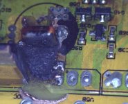
Here's another clue.blown2.jpg

As you can see one of the fet legs melted. This is the seventh fet from the wiring end (phase B low side?).

Here are some measurements before I start removing fets.

Phase B shorted to GND

Phase C shorted to VCC

50 ohms VCC to GND.
 
Hi Mike,
It looks to me if it was heat related and maybe not a faulty component , after your last ride or maybe over some time the connection to that fet leg was not a very good one and generated a lot of isolated heat which caused the board to burn which then would have cause a resistive path between the tracks then this can then go into a melt down situation. This is just my slant on it, I have seen this type of fault many times but normally on a lot higher voltage.
 
My last ride was quite hard, around 9KW, so I suppose that's possible.

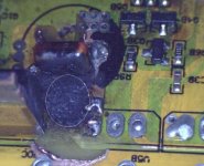
I've got the phase B low side fets out now (all shorted) and also that large electrolytic so we can get a better look at it.

blown3.jpg

Haven't removed the phase c high side fets yet but am guessing they will all be shorted too.
 
Hi Mike,
These resistive paths caused by the burning of the pcb can cause components to fail due to voltages going into places that they are not sposed to go, but the more I look at the pictures the more I think this is whats happened. I will have a look at my 18fet controller when I get back home just to see if there are any sm components that should be in this area. I think the main clue is the fact that the main area of burnt board do not contain any components.
blown3.jpg
 
I don't think there are any components there. There's a picture of the top of the board posted in the first page of this thread. http://www.endless-sphere.com/forums/download/file.php?id=22322

Not sure if this board is scrap now or if I'm going to be able to remove the charring. :(
 
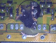
Got that small cap out now. Also took out the phase C high side fets, one shorted, other two seem OK. Anyone got a definitive guide on testing mosfets with a multimeter?blown4.jpg
 
just looked at the board picture your right there is nothing else there ( I forgot I dont have a 18fet controller its a 12fet :lol: ) I would be very cautious re-using the board pulling that sort of current thought it on a regular basis, I think I would buy a replacement controller and keep that controller as a spare/backup.
 
I think you may be right. I could just transfer all the wires over to a new board. I'd keep the other for parts for when I blow the new one up :shock:

So does anyone in the UK have an 18 fet board and 4110 fets?
Geoff, you got one?

:?:
 
Mike1 said:
I think you may be right. I could just transfer all the wires over to a new board. I'd keep the other for parts for when I blow the new one up :shock:

So does anyone in the UK have an 18 fet board and 4110 fets?
Geoff, you got one?

:?:

I have a brand new , unused, 18 FET Infineon board and case, with FET mounting hardware but with no FETs fitted.

I'm near Salisbury if you're anywhere near, or I could stick it in the post to you.

Jeremy
 
I'm afraid not, it's one I bought from Keywin just before the 116 came out.

Jeremy
 
Mike1 said:
Hi Jeremy, is that the instant start 116 board?
Jeremy Harris said:
I'm afraid not, it's one I bought from Keywin just before the 116 came out.

Hi Jeremy,
I am a bit confused by this instant start thing :?: ( it dont take much I know :lol: ) , My first controller is one of the old 6fet
controllers and there is no sign of lag in the throttle i since bought a newer 6fet (116) and I had no end of trouble with it at first it will not always start ( it would start only if you wound on the throttle very slowly ) I have now since resolved this by adjusting the timimg slightly. Have you experienced this slow start issue first hand or was it only a problem on some of the older bigger controllers as far as you know.
 
Mike1 said:
Got that small cap out now. Also took out the phase C high side fets, one shorted, other two seem OK. Anyone got a definitive guide on testing mosfets with a multimeter?

What i do needs a little bit practice... here goes description for N-type testing.

First i discharge gate touching with probes (- or black to gate + or red to source), then i measure drain source both directions, when minus is on drain i got reverse diode 400mV drop, and with plus on the drain i got O.L. (max voltage or high resistance, yeah testing must be done with diode test, multimeter used must be capable of putting put more then 3Vdc on the test leads in diode mode, so far all of my DVM's were capable testing mosfets).
Now here comes the trick, with minus touching source i touch gate with plus (red) and charge the gate, that opens the mosfet, and then checking Drain Source with plus on the drain, mosfet look shorted, and DVM makes beep tone showing few mV of voltage drop on the display.
Now i hook up plus to the source, and again with black i touch the gate, discharging the gate, and check the Drain Source again, it should be "open" with O.L. again...
Works like a charm pretty dependable results there...
z
 
HOW TO REPAIR:

14V and 5V regulator problem

Cause: Controller stopped working just after you connect the battery to it and you are not using any precharge resistor to smooth the current to start the controller anc charging the controller internal capacitors...
it stopped working right after you heard that "normal... usuall' spark on the plug


HOW TO REPAIR:

it might be the famous MPSA93 transistor ( Q2)

I repaired a 100V controller that is using 28s a123 ( 100V) that did not have any pre charge resistor.. and that spark have make it stop working.

After few hours of investigations, i discovered that it's that Q2 transistor that was deffective.

The symptom was:

Low 5V at the output of the 7805 regulator ( U100).. I measured 4.5V instead of 5V... but the 14V rail that usually supply it, was at 6,5V and not 14V.. so i suspected that it was not the 5V the problem.. but almost the 14V that was at 6.5V.

Replacing the MPSA93 solved the problem

I know someone that will be very happy to use his newly WORKING controller this weekend! :wink: CHXS

Doc
 
Now i will precharge my controller ... :twisted: Tanks to an awsome doc :p I will enjoy the torque of my bike :)

Chris
 
Good work doc.
That is a little chunk of knowledge that we should preserve somehow.
Nothing like troubleshooting shortcuts!

-methods
 
Does anyone have the schematic of the infineon 12 or 18 fets instant start controller?

I remember i already saw it onthe E-S.. it was in many seperate pages.. pdf?

I'm looking for the output fets driver shcematics cause i have mine that seem to have one phase having a problem.. but all mosfets are good and the hall sensor are good too.. :|

It make the hub to turn but make a very loud noise and vibrate alot.. and. yes!... the phase connection are ok

When i use very low throttle, the wheel can rotate very low.. but itMs like one phase have a positive or negative side missing....

it just happened while i used it...

- hall sensor OK
- Phase connection OK
- Motor ok ( i tested with another controller and it work)
- Mosfet OK ( every 3 phases test above 10 kohm from the positive and negative rail)
fet driver ????

I'll put that o a scopemeter tomorrow and will see what happen on these 3 phase while the motor rotate

Doc
 
Back
Top