• Hello ES! We could use some help to get us past the finish line on building the new knowledgebase for the forum.
    Can you donate? Please see our fundraising page. Thank you!

jonescg's eCRX pre-build thread!

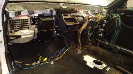
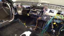
I started to re-install the HVAC and associated wiring looms. Also started to work out where to run the various HV cables - looks like the only way I can get them into the engine bay is via the cabin - the sway bar is too close to the bottom of the chassis so I can't sneak it under. Probably not a bad outcome since the main cable to the battery is likely to be inside the cabin too.
 

Attachments

  • Cabin HVAC reinstalled 2.jpg
    Cabin HVAC reinstalled 2.jpg
    198.4 KB · Views: 12
  • Cabin HVAC reinstalled 1.jpg
    Cabin HVAC reinstalled 1.jpg
    219.9 KB · Views: 11
Being a front wheel drive, there's only a tunnel where the gear shift rods and exhaust went, but that's not the problem. The problem is the sway bar with it's raised bend (to clear the exhaust and gear shift rods) is just so damn close to the body I risk pinching the cables.
I think having the cables accessible inside isn't a bad idea though, as I can access them for coulomb counting.
 
Charger stack is mounted and the shelf will provide support for things like the HV power distribution box, charging management, drive control and all the 12 V relays and fuses for ancillaries.
 

Attachments

  • Charge stack mounted2.jpg
    Charge stack mounted2.jpg
    372.3 KB · Views: 20
  • Charge stack mounted1.jpg
    Charge stack mounted1.jpg
    355.3 KB · Views: 19
  • Charger support shelf 6.jpg
    Charger support shelf 6.jpg
    268.6 KB · Views: 19
I probably should have either pulled out ALL of the 12 V wiring and started again, or left almost all of it in place and worked around it. I wanted to build a new HVAC control panel and a new dash cluster, so much of the old wiring had to come out, but it took a lot of the essential wiring with it. So while it feels like I made progress this week, I'm barely back to where I started. At least now I understand the wiring loom like the back of my hand.
 
Yeah this is all about making sure the car is simpler, as well as electric. Much of the wiring inside the cabin was unnecessary (old engine control units and sensors etc) but in pulling that stuff out, I took out a lot of the wiring I needed to keep, especially the links to the rear of the vehicle.

Now the main tasks are to set the inverter controls up (throttle, brake, direction control) and then prepare for the main traction battery with contactors, precharge circuits and start-up/shut-down systems. I'll jury-rig some kind of 350 V battery so I can start trying to get it to turn a wheel.

Only then will I bother planning for the final battery.
 
Small update: The 12 V wiring and fuses in the footwell are looing better. Not as neat as the original, but definitely simpler.
I also wired up the HVAC loom so now the AC compressor is activated in parallel with the condenser fan relay. The fan is blowing, not pushing, so it isn't very effective. I might try to find four 4" fans to do the exposed ends of the condenser from the inside.
Next step - inverter control wiring loom, and a centre console control panel for the climate control, stereo and accessories (12 V cigarette lighter adaptor, USB charge port and the RS232 output from the inverter for tuning.
 

Attachments

  • new fuse box.jpg
    new fuse box.jpg
    221.2 KB · Views: 5
  • AC compressor and Condensor fan relay.jpg
    AC compressor and Condensor fan relay.jpg
    177.3 KB · Views: 5
Been a while since I last posted an update; I'm a bit more active on the AEVA forum.
Dash back in.jpeg
The dash has gone back in - decided against a fully custom dash. Just way too hard in the time I have. But I have started work on the instrument cluster and direction control.
instrument cluster.jpeg

But the HV power distribution box is taking shape, as is the space to secure it.
HVPDU box latest.jpeg
My goal is to have this ready for a battery in February or thereabouts.
 

Attachments

  • Climate and instrument.jpeg
    Climate and instrument.jpeg
    154.8 KB · Views: 9
  • New instrument cluster ideas.jpeg
    New instrument cluster ideas.jpeg
    187.2 KB · Views: 8
  • New start button.jpg
    New start button.jpg
    193 KB · Views: 8
  • ChargeDriveStartBoxCircuit.png
    ChargeDriveStartBoxCircuit.png
    115.3 KB · Views: 10
  • Engine bay so far.jpg
    Engine bay so far.jpg
    288.3 KB · Views: 11
Minor background progress - the instrument cluster and binnacle are coming together, and the climate control panel is getting closer - I had no idea how it would fit until I made it, so I'll be re-making that one :)
In other news, I have ordered 70 kg of thermally conductive, electrically insulating epoxy resin. I reckon only need about 10 kg, so any Aussie battery builders who want some potted options should get in touch.
I'm also looking into cell options - I want to use 21700s just because there's fewer of them to weld up, and the INR21700-50S looks promising. Apparently good for 35 A continuous. I'm after 30 kWh, and it needs to fit within a block 300 mm x 400 mm x 700 mm. Could be an option...
 

Attachments

  • Climate control panel fitment.jpeg
    Climate control panel fitment.jpeg
    160.1 KB · Views: 7
  • Binnacle in 2.jpeg
    Binnacle in 2.jpeg
    130.4 KB · Views: 7
  • Binnacle in.jpeg
    Binnacle in.jpeg
    128.8 KB · Views: 7
Putting some serious thought into the battery now...
Those dark coloured circles are where 21 mm diameter tube will go so that the complete module has multiple holes in it from one side through to the other. Then I can sandwich 7 cooling plates together with 8 modules and have a really good axially cooled battery pack.
 

Attachments

  • 21700 batery CRX.png
    21700 batery CRX.png
    348.5 KB · Views: 10
I doubt I'd need all of the holes for threaded rods, but 6 of them would be a solid assembly with 7 cooling plates. Goal is to get the cooling plates under 10 mm thick...
 

Attachments

  • 3D battery assembly holes.png
    3D battery assembly holes.png
    35.8 KB · Views: 4
  • 3D battery assembly.png
    3D battery assembly.png
    117.6 KB · Views: 5
A little bit of progress to report on the car - the house battery has kept me busy! Plus it's stinking hot in the shed now.
I've decided that the total abortion of wiring, soldered wires, and re-soldered wires was a mess, and was likely responsible for the fact the climate panel worked once, and then stopped working.
centre console wiring mess.jpeg
No fuses popped, but I think I might have trouble with the grounds. Because the AC and HEAT buttons are DPDT and both LED illuminated, and they cannot function unless the blower fan is on, I'm running the grounds through the switch on the blower fan knob.
Climate panel wiring.png
This way, the AC and the ceramic heater core can't be on unless there's airflow across the evaporator and heater element respectively. But I think that ground was not done right. The mess was pretty bad for troubleshooting, but also impossible tin install and pull apart with ease. So I bought two new ones and made a better go of it, this time with multi-pin connectors for each switch.
Climate panel connectors.jpeg
This *should* make assembly a bit easier to follow. I have also started to run the pilot wires up to the dash for things like P-R-N-D etc, and the direction control wires to the inverter, as well as an unswitched +12 V source for the stereo since it's going to be a pest to find new stations each time you turn the car off.

I've also started making plans for the battery. Each module will be made from 240 individual 21700-format cells in a 12s20p arrangement, held together by two capture plates machined form polycarbonate. The bus plates will be 0.8 mm thick copper, and the tabs linking the cell ends to the bus plates will be nickel with a copper foil sandwich. This results in a much lower resistance link, allowing over 50 amps per cell to be drawn.

The modules will have thermally conductive epoxy slathered all over the final bus terminations on each side, and a layer of 0.8 mm G10FR4 to seal it together. The terminals will involve PCBs with 13-way cell tap connectors and two 2-way connectors for the thermistors. This means I have BMS options when the 8 modules are stacked together.

The holes will go right through the battery, as each block of cells has 21 spaces - one is blank for each hole. I don't need all these holes, but I'm sure it will come in handy at some point - I'll use 6 of them for M10 threaded rods to clamp all 8 modules and 7 liquid cooling plates together. The cooling plates won't be machined from a slab of aluminium - instead I'll do what I did for the Prelude cooling plates and have them laser cut. A few countersunk M3 screw holes help hold them all together, but RTV silicone will be doing the bulk of the work.
Coolingplate assembly.png
The idea is to have an inlet at the bottom and an outlet at the top. These will all be in parallel with 10 mm vinyl tube, and coolant will circulate in through the bottom and out from the top, back to the heat exchanger. The inlet and outlet will need to be out the back because there's too much going on in the front of the battery to have plumbing in the way as well.
3D battery assembly with cooling plate.png
So the theory goes anyway, we'll see how I get on before now and return to work...
 
Wiring up the PM100 today in the shed. I hope to be able to start tuning the inverter to the motor soon, but I'll have to strap a few batteries together for that...
Also made sure the coulomb counter is working and the coolant pumps are supplied by their own relay, which is activated whenever the car is on charge or driving.
I even bled the brakes, although it's going to need doing again when I'm a bit closer to a test drive.
 

Attachments

  • PM100 wiring2.jpeg
    PM100 wiring2.jpeg
    207.5 KB · Views: 4
  • PM100 wiring1.jpeg
    PM100 wiring1.jpeg
    190.8 KB · Views: 4
PCBs sent off for fabrication. The Everything board is the charge/drive/BMS driver board, while the drive control board is literally about shifting the car into Park, Reverse, Neutral and Drive (but with LEDs).
 

Attachments

  • Drive control PCB model.png
    Drive control PCB model.png
    88.9 KB · Views: 4
  • Everything PCB model.png
    Everything PCB model.png
    83.3 KB · Views: 4
I'm going to use copper busplates with 19 mm diameter holes where the cell terminals will be accessed, and linking the cell to the busplate with a nickel-copper tab. As I have posted elsewhere, the 0.1 mm nickel with a 0.07 mm thick bit of copper foil makes for a pretty robust connection and they can be spotwelded with a conventional transformer based spot welter.

But a big point of frustration was trying to fuse the sandwich tab to the copper bus plate. I used to solder them flat on the top and bend the link down into the 19 mm hole for welding to the cell, but it was hard to know that the fusion was as good as it should be. So this time I'm trying a 1 mm wide slot cut into the copper where I can slip the tab in, bend it over, and solder the tab leaving a tight nugget of tin between the sandwich and the copper busplate. I'm testing the current carrying capability of the cells terminated this way on the weekend, so here's my test pieces:

I'll try and unload a constant 50 A from a single Molicell and see how it goes. Even 35 A would be amazing - at 20p, that's 700 A.
 

Attachments

  • copper nickel sandwich1.jpeg
    copper nickel sandwich1.jpeg
    133 KB · Views: 8
  • copper nickel sandwich2.jpeg
    copper nickel sandwich2.jpeg
    131.5 KB · Views: 7
  • copper nickel sandwich3.jpeg
    copper nickel sandwich3.jpeg
    114.8 KB · Views: 8
  • copper nickel sandwich4.jpeg
    copper nickel sandwich4.jpeg
    125.5 KB · Views: 8
Back
Top